
Technical Product Specification

System Power Sub-system Intel® Server System P4000IP and Intel® Workstation System P4000CR Family TPS
Revision 1.2 Intel order number G38159-002
67
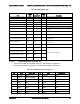
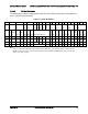
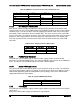
Table 69. PDB Cable Length
From
Length,
mm
To
connector #
No of
pins
Description
Power Supply cover exit hole
470
P1
24
Baseboard Power Connector
Power Supply cover exit hole
320
P2
8
Processor 0 connector
Power Supply cover exit hole
450
P3
8
Processor 1 connector
Power Supply cover exit hole
800
P4
5
Power FRU/PMBus connector
Power Supply cover exit hole
350
P5
5
SATA peripheral power connector for 5.25''
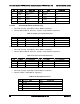
Extension from P5
100
P6
5
SATA peripheral power connector for 5.25''
Extension from P6
100
P7
4
Peripheral Power Connector for 5.25''/HSBP
Power
Power Supply cover exit hole
400
P8
4
1x4 legacy HSBP Power Connector
Extension from P8
75
P9
4
1x4 legacy HSBP Power Connector
Power supply cover exit hole
500
P10
4
1x4 legacy HSBP Power/Fixed HDD adaptor
Connection
Extension from P10
75
P11
4
1x4 legacy HSBP Power/Fixed HDD adaptor
Connection
PCI power connector
800
P12
4
2x2 Legacy PCI Power Connector
Connector only (no cable)
n/a
P13
4
GFX card aux connectors
Connector only (no cable)
n/a
P14
4
Connector only (no cable)
n/a
P15
4
Connector only (no cable)
n/a
P16
4
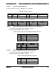
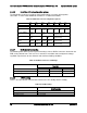
2.4.2.2.1 Baseboard power connector (P1)
Connector housing: 24-Pin Molex* Mini-Fit Jr. 39-01-2245 or equivalent
Contact: Molex* Mini-Fit, HCS Plus, Female, Crimp 44476 or equivalent
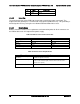
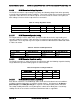
Table 70. P1 Baseboard Power Connector
Pin
Signal
18 AWG Color
Pin
Signal
18 AWG Color
1
+3.3VDC
Orange
13
+3.3VDC
Orange
3.3V RS
Orange (24AWG)
2
+3.3VDC
Orange
14
-12VDC
Blue
3
COM
Black
15
COM
Black
4
+5VDC
Red
16
PSON#
Green (24AWG)
5
COM
Black
17
COM
Black
6
+5VDC
Red
18
COM
Black
7
COM
Black
19
COM
Black