
Technical Product Specification

System Power Sub-system Intel® Server System P4000IP and Intel® Workstation System P4000CR Family TPS
Revision 1.2 Intel order number G38159-002
57
2.3.4.10 Forced Load Sharing
The +12V output will have active load sharing. The output will share within 10% at full load. The
failure of a power supply should not affect the load sharing or output voltages of the other
supplies still operating. The supplies must be able to load share in parallel and operate in a hot-
swap/redundant 1+1 configurations. The 12VSB output is not required to actively share current
between power supplies (passive sharing). The 12VSB output of the power supplies are
connected together in the system so that a failure or hot swap of a redundant power supply
does not cause these outputs to go out of regulation in the system.
2.3.4.11 Ripple/Noise
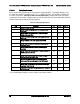
The maximum allowed ripple/noise output of the power supply is defined in Table below. This is
measured over a bandwidth of 10Hz to 20MHz at the power supply output connectors. A 10F
tantalum capacitor in parallel with a 0.1F ceramic capacitor is placed at the point of
measurement.
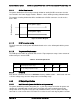
Table 60. Ripples and Noise
+12V main
+12VSB
120mVp-p
120mVp-p
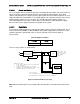
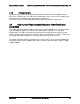
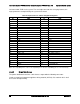
The test set-up shall be as shown below.
AC HOT
POWER SUPPLY
AC NEUTRAL
V
OUT
RETURN
V
AC GROUND
LOAD
SCOPE
LOAD MUST BE
ISOLATED FROM
THE GROUND OF
THE POWER
SUPPLY
10uF
.1uF
GENERAL NOTES:
1. LOAD THE OUTPUT WITH ITS MINIMUM
LOAD CURRENT.
2. CONNECT THE PROBES AS SHOWN.
3. REPEAT THE MEASUREMENTS WITH THE
MAXIMUM LOAD ON THE OUTPUT.
SCOPE NOTE:
USE A TEKTRONIX 7834 OSCILLOSCOPE WITH 7A13 AND
DIFFERENTIAL PROBE P6055 OR EQUIVALENT.
Figure 25. Differential Noise test setup
Note: When performing this test, the probe clips and capacitors should be located close to the
load.