
Technical Product Specification

Intel® Server System P4000IP and Intel® Workstation System P4000CR Family TPS System Power Sub-system
24 Intel order number G38159-002 Revision 1.2
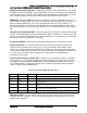
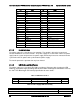
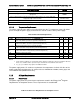
Pin
Name
Pin
Name
A6
GND
B6
GND
A7
GND
B7
GND
A8
GND
B8
GND
A9
GND
B9
GND
A10
+12V
B10
+12V
A11
+12V
B11
+12V
A12
+12V
B12
+12V
A13
+12V
B13
+12V
A14
+12V
B14
+12V
A15
+12V
B15
+12V
A16
+12V
B16
+12V
A17
+12V
B17
+12V
A18
+12V
B18
+12V
A19
PMBus SDA
B19
A0 (SMBus address)
A20
PMBus SCL
B20
A1 (SMBus address)
A21
PSON
B21
12V stby
A22
SMBAlert#
B22
Cold Redundancy Bus
A23
Return Sense
B23
12V load share bus
A24
+12V remote Sense
B24
No Connect
A25
PWOK
B25
Compatibility Check pin
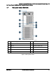
2.1.1.2 Handle Retention
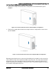
The power supply has a handle to assist extraction. The module is able to be inserted and
extracted without the assistance of tools. The power supply has a latch which retains the power
supply into the system and prevents the power supply from being inserted or extracted from the
system when the AC power cord is pulled into the power supply.
The handle protects the operator from any burn hazard.
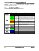
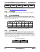
2.1.1.3 LED Marking and Identification
The power supply uses a bi-color LED: Amber and Green. Below are table showing the LED
states for each power supply operating state and the LED’s wavelength characteristics. Refer to
the Intel
®
LED Wavelength and Intensity Specification for more details.
Table 7. LED Characteristics
Min λd Wavelength
Nominal λd Wavelength
Max λd Wavelength
Units
Green
562
565
568
nm
Amber
607
610
613
nm
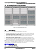
Table 8. Power Supply LED Functionality
Power Supply Condition
LED State
Output ON and OK
GREEN
No AC power to all power supplies
OFF