
Technical Product Specification

Storage and Peripheral Drive Bays Intel® Server System P4000IP and Intel® Workstation System P4000CR Family TPS
Revision 1.2 Intel order number G38159-002
93
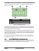
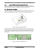
Each connector on the SAS expander card can be used as a “cable in” (SAS Controller to SAS
Expander) or “cable out” (SAS Expander to Hot Swap Backplane) type connector. However, for
contiguous drive mapping (0 – 16 or 0 – 24), cable routing differs when using a x8 wide-port
capable 6 Gb SAS/SAS RAID Controller vs. using the embedded SCU ports.
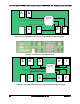
4.3.1.1 Cable Routing using a x8 wide-port capable 6 Gb SAS/SAS RAID Controller
To ensure contiguous drive mapping when using x8 wide-port capable 6 Gb SAS/SAS RAID
Controller with a SAS expander card, the system must be cabled as follows:
Cables from the SAS Expander to the hot swap backplane must be connected in order:
A – D for 16-drive configurations, and A – F for 24 drive configurations.
The cables from the SAS controller can be attached to any of the remaining connectors
on the SAS expander card.
4.3.1.2 Cable Routing using the embedded SCU ports
Note: The following may also be applied when using any 3 Gb SAS/SAS RAID Controller.
For storage configurations that utilize up to 16 or 24 hard disk drives for storage only and an
internally mounted SSD as a boot device, the system must be configured as follows to
ensure contiguous drive mapping (0 – 16 or 0-24):
At least one internally mounted SSD device must be attached to the AHCI controller
(SATA_0 or SATA_1 on the server board) and used as a boot device.
Cables from the SAS Expander to the hot swap backplane must be connected in order:
B – E for 16-drive configurations, and B – G for 24 drive configurations.
The SCU_0 or 3G SAS/SAS RAID (0-3) connector is cabled to the first mini-SAS
connector on the hot swap backplane
The SCU_1 or 3G SAS/SAS RAID (4-7) connector is cable to Connector A on the SAS
expander card.
For storage configurations that require utilizing a hard disk drive as the boot device, the
system must be cabled as follows to ensure a boot device is found and for contiguous drive
mapping (0-16 or 0-24).
The SCU_0 (0-3) connector on the server board is cabled to the first mini-SAS
connector on the hot swap backplane
The SCU_1 (4-7) connector on the server board is cable to Connector_A on either the
24-port or 36-port SAS expander card.
Cables from the SAS Expander to the hot swap backplane must be connected in
order: B – F on the 24-port expander card, and B – G on the 36-port expander card.
Note: Current SCU controller design limitations prevent any hard drive attached to a SAS
expander card from being a boot device when both SCU connectors are attached to the SAS
expander card.
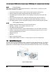
Please reference the Intel
®
Server System P4000IP Product Family Service Guide for cable
routing diagrams illustrating a variety of storage configurations.