
Technical Product Specification

Platform Management Overview Intel® Server Board S2600IP and Intel® Workstation Board W2600CR TPS
60 Intel order number G34153-004 Revision 1.4
At BMC startup, the BMC will check for the fault condition and set the sensor state accordingly.
The BMC also checks for this fault condition at each attempt to DC power-on the system. At
each DC power-on attempt, a beep code is generated if this fault is detected. Please refer Table
9 (BMC Beep Codes) for beep code details.
The following steps are used to correct the fault condition and clear the sensor state:
1. AC power down the server.
2. Install the missing processor into the correct slot.
3. AC power on the server.
Refer to the applicable platform BMC EPS as to the details of what population rules must be
followed.
4.3.4.3 ERR2 Timeout Monitoring
The BMC supports an ERR2 Timeout Sensor (1 per CPU) that asserts if a CPU’s ERR2 signal
has been asserted for longer than a fixed time period (> 90 seconds). ERR2 is a processor
signal that indicates when the IIO (Integrated IO module in the processor) has a fatal error
which could not be communicated to the core to trigger SMI. ERR[2] events are fatal error
conditions, where the BIOS and OS will attempt to gracefully handle error, but may not be
always do so reliably. A continuously asserted ERR2 signal is an indication that the BIOS
cannot service the condition that caused the error. This is usually because that condition
prevents the BIOS from running.
When an ERR2 timeout occurs, the BMC asserts/deasserts the ERR2 Timeout Sensor, and
logs a SEL event for that sensor. The default behavior for BMC core firmware is to initiate a
system reset upon detection of an ERR2 timeout. The BIOS setup utility provides an option to
disable or enable system reset by the BMC for detection of this condition.
IPMI Sensor Characteristics
1. Event reading type code: 03h (Generic – digital discrete)
2. Sensor type code: 07h (Processor)
3. Rearm type: Auto
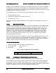
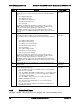
Table 18. Supported ERR2 Timeout Sensor Offsets
Offset
Description
Event Logging
01h
State asserted
Assertion and deassertion
4.3.4.4 CATERR Sensor and Market Segment ID (MSID) Mismatch
The BMC supports a CATERR sensor for monitoring the system CATERR signal.
The CATERR signal is defined as having 3 states; high (no event), pulsed low (possibly fatal
may be able to recover), and low (fatal). All processors in a system have their CATERR pins
tied together. The pin is used as a communication path to signal a catastrophic system event to
all CPUs. The BMC has direct access to this aggregate CATERR signal.