
Technical Product Specification

Intel® Server Board S2600IP and Intel® Workstation Board W2600CR TPS Functional Architecture
Revision 1.4 Intel order number G34153-004 31
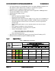
The following are generic DIMM population requirements that generally apply to both the Intel
®
Server Board S2600IP and Intel
®
Workstation Board W2600CR.
DIMM slots on any memory channel must be filled following the “farthest fill first” rule.
A maximum of 8 ranks can be installed on any one channel, counting all ranks in each
DIMM on the channel.
DIMM types (UDIMM, RDIMM, LRDIMM) must not be mixed within or across processor
sockets.
Mixing ECC with non-ECC DIMMs (UDIMMs) is not supported within or across
processor sockets.
Mixing Low Voltage (1.35V) DIMMs with Standard Voltage (1.5V) DIMMs is not
supported within or across processor sockets.
Mixing DIMMs of different frequencies and latencies is not supported within or across
processor sockets.
LRDIMM Rank Multiplication Mode and Direct Map Mode must not be mixed within or
across processor sockets.
Only ECC UDIMMs support Low Voltage 1.35V operation.
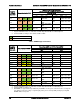
QR RDIMMs may only be installed in DIMM Slot 1 or 2 on a channel.
2 DPC QR Low Voltage RDIMMs are not supported.
In order to install 3 QR LRDIMMs on the same channel, they must be operated with
Rank Multiplication as RM = 2.
RAS Modes Lockstep, Rank Sparing, and Mirroring are mutually exclusive in this BIOS.
Only one operating mode may be selected, and it will be applied to the entire system.
If a RAS Mode has been configured, and the memory population will not support it
during boot, the system will fall back to Independent Channel Mode and log and display
errors
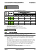
Rank Sparing Mode is only possible when all channels that are populated with memory
meet the requirement of having at least 2 SR or DR DIMM installed, or at least one QR
DIMM installed, on each populated channel.
Lockstep or Mirroring Modes require that for any channel pair that is populated with
memory, the memory population on both channels of the pair must be identically sized.
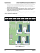
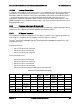
DIMM population rules require that DIMMs within a channel be populated starting with the BLUE
DIMM slot or DIMM farthest from the processor in a “fill-farthest” approach. In addition, when
populating a Quad-rank DIMM with a Single- or Dual-rank DIMM in the same channel, the
Quad-rank DIMM must be populated farthest from the processor. Note that Quad-rand DIMMs
and UDIMMs are not allowed in three slots populated configurations. Intel MRC will check for
correct DIMM placement.
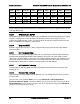
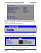
3.2.2.3 Publishing System Memory
The BIOS displays the “Total Memory” of the system during POST if Display Logo is
disabled in the BIOS setup. This is the total size of memory discovered by the BIOS
during POST, and is the sum of the individual sizes of installed DDR3 DIMMs in the
system.