
Technical Product Specification


Intel® Server Board S2600IP and Intel® Workstation Board W2600CR TPSAppendix D: POST Code Diagnostic LED Decoder
Revision 1.4 Intel order number G34153-004 157
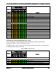
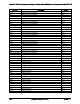
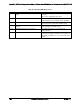
Checkpoint
Diagnostic LED Decoder
Description
1 = LED On, 0 = LED Off
Upper Nibble
Lower Nibble
MSB
LSB
8h
4h
2h
1h
8h
4h
2h
1h
LED #
#7
#6
#5
#4
#3
#2
#1
#0
B2h
1
0
1
1
0
0
1
0
DXE Legacy Option ROM init
B3h
1
0
1
1
0
0
1
1
DXE Reset system
B4h
1
0
1
1
0
1
0
0
DXE USB Hot plug
B5h
1
0
1
1
0
1
0
1
DXE PCI BUS Hot plug
B6h
1
0
1
1
0
1
1
0
DXE NVRAM cleanup
B7h
1
0
1
1
0
1
1
1
DXE Configuration Reset
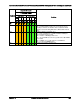
00h
0
0
0
0
0
0
0
0
INT19
S3 Resume
E0h
1
1
0
1
0
0
0
0
S3 Resume PEIM (S3 started)
E1h
1
1
0
1
0
0
0
1
S3 Resume PEIM (S3 boot script)
E2h
1
1
0
1
0
0
1
0
S3 Resume PEIM (S3 Video Repost)
E3h
1
1
0
1
0
0
1
1
S3 Resume PEIM (S3 OS wake)
BIOS Recovery
F0h
1
1
1
1
0
0
0
0
PEIM which detected forced Recovery condition
F1h
1
1
1
1
0
0
0
1
PEIM which detected User Recovery condition
F2h
1
1
1
1
0
0
1
0
Recovery PEIM (Recovery started)
F3h
1
1
1
1
0
0
1
1
Recovery PEIM (Capsule found)
F4h
1
1
1
1
0
1
0
0
Recovery PEIM (Capsule loaded)
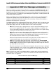
POST Memory Initialization MRC Diagnostic Codes
There are two types of POST Diagnostic Codes displayed by the MRC during memory
initialization; Progress Codes and Fatal Error Codes.
The MRC Progress Codes are displays to the Diagnostic LEDs that show the execution point in
the MRC operational path at each step.
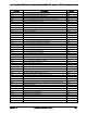
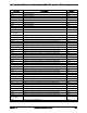
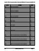
Table 84. MRC Progress Codes
Checkpoint
Diagnostic LED Decoder
Description
1 = LED On, 0 = LED Off
Upper Nibble
Lower Nibble
MSB
LSB
8h
4h
2h
1h
8h
4h
2h
1h
LED
#7
#6
#5
#4
#3
#2
#1
#0
MRC Progress Codes
B0h
1
0
1
1
0
0
0
0
Detect DIMM population
B1h
1
0
1
1
0
0
0
1
Set DDR3 frequency
B2h
1
0
1
1
0
0
1
0
Gather remaining SPD data
B3h
1
0
1
1
0
0
1
1
Program registers on the memory controller level
B4h
1
0
1
1
0
1
0
0
Evaluate RAS modes and save rank information