
Technical Product Specification

Connector/Header Locations and Pin-outs Intel® Server Board S2600IP and Intel® Workstation Board W2600CR TPS
102 Intel order number G34153-004 Revision 1.4
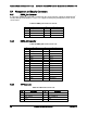
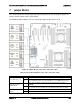
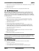
Figure 29. Video Connector Pin-out
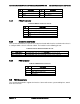
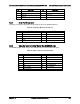
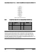
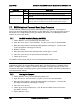
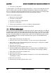
6.6.4 Internal Video Header (For Intel® Workstation Board W2600CR only)
Pin
Signal Name
Pin
Signal Name
1
CRT_RED
2
GND
3
CRT_Green
4
GND
5
CRT_Blue
6
GND
7
CRT_VSYNC
8
GND
9
CRT_HSYN
10
Key
11
CRT_DDCDATA
12
VIDEO_IN_USE signal
13
CRT_DDCCLK
14
5V
Note: Intel Corporation server boards support peripheral components and can contain a number
of high-density VLSI and power delivery components that need adequate airflow to cool. Intel’s
own chassis are designed and tested to meet the intended thermal requirements of these
components when the fully integrated system is used together. It is the responsibility of the
system integrator that chooses not to use Intel developed server building blocks to consult
vendor datasheets and operating parameters to determine the amount of airflow required for
their specific application and environmental conditions. Intel Corporation cannot be held
responsible if components fail or the server board does not operate correctly when used outside
any of its published operating or non-operating limits.