
Technical Product Specification

Connector/Header Locations and Pin-outs Intel® Server Board S2600IP and Intel® Workstation Board W2600CR TPS
100 Intel order number G34153-004 Revision 1.4
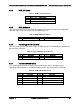
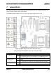
6.5.1 System FAN Connectors
The six system cooling fan connectors near the front edge of the board are 6-Pin connectors;
the one system cooling fan near edge of the board is a 4-Pin connectors. Following table
provides the pin-out for all system fan connectors.
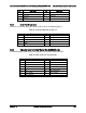
Table 51. 6-pin System FAN Connector Pin-out
Pin
Signal Name
1
GND
2
12V
3
TACH
4
PWM
5
PRSNT
6
FAULT
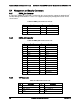
Table 52. 4-pin System FAN Connector Pin-out
Pin
Signal Name
1
GND
2
12V
3
TACH
4
PWM
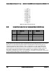
6.5.2 CPU FAN Connector
The two CPU fan connectors are 4-pin fan connectors. Following table provides the pin-out for
CPU fan connectors.
Table 53. CPU FAN Connector Pin-out
Pin
Signal Name
1
GND
2
12V
3
TACH
4
PWM
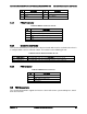
6.6 Serial Port and Video Connectors
The server board includes two serial port connectors.
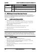
6.6.1 Serial Port A Connector (DB9, for Intel® Server Board S2600IP only)
Serial-A is an external RJ45 type connector and has the following pin-out configuration.
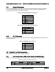
Table 54. Serial Port A Connector Pin-out
Pin
Signal Name
Pin
Signal Name
1
SPA_DCD
2
SPA_SIN