
Technical Product Specification

Intel® Server Board S2600IP and Intel® Workstation Board W2600CR TPS Connector/Header Locations and Pin-outs
Revision 1.4 Intel order number G34153-004 95
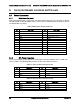
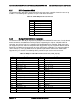
6.3.1 SATA Connectors: 6Gb/s
The board includes two white single port SATA only connectors capable of transfer rates of up
to 6Gb/s. The following table provides the pin-out for both connectors.
Table 37. SATA 6Gbps Connector Pin-out
Pin
Signal Name
1
GND
2
SATA_TX_P
3
SATA_TX_N
4
GND
5
SATA_RX_N
6
SATA_RX_P
7
GND
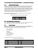
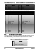
6.3.2 Multiport Mini-SAS/SATA Connectors
The board includes two 40-pin high density multiport mini-SAS/SATA connectors. On the board,
these connectors are labeled as “SCU0 port(0-3)” supporting the chipset embedded SCU0
controller, and “SCU1 Port(4-7)”, supporting the embedded SCU1 controller. Both connectors
can support up to four SATA or SAS ports each. By default, only the connector labeled “SCU0
Port(0-3)” is enabled and has support up to four SATA ports capability. The connector labeled
“SCU1 Port(4-7)” is only enabled when an optional 8-port SAS or SATA Intel
®
RAID C600
Upgrade Key is installed. The following tables provide the pin-out for each connector.
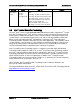
Table 38. Multiport SAS/SATA Connector Pin-out ("SCU_0 (0-3)")
Pin
Signal Name
Pin
Signal Name
A1
GROUND
B1
GROUND
A2
SAS0_RX_C_DP
B2
SAS0_TX_C_DP
A3
SAS0_RX_C_DN
B3
SAS0_TX_C_DN
A4
GROUND
B4
GROUND
A5
SAS1_RX_C_DP
B5
SAS1_TX_C_DP
A6
SAS1_RX_C_DN
B6
SAS1_TX_C_DN
A7
GROUND
B7
GROUND
A8
TP_SAS1_BACKPLANE_TYPE
B8
SGPIO_SAS1_CLOCK
A9
GROUND
B9
SGPIO_SAS1_LOAD
A10
SGPIO_SAS1_DATAOUT
B10
GROUND
A11
SGPIO_SAS1_DATAIN
B11
PD_SAS1_CONTROLLER_TYPE
A12
GROUND
B12
GROUND
A13
SAS2_RX_C_DP
B13
SAS2_TX_C_DP
A14
SAS2_RX_C_DN
B14
SAS2_TX_C_DN
A15
GROUND
B15
GROUND
A16
SAS3_RX_C_DP
B16
SAS3_TX_C_DP
A17
SAS3_RX_C_DN
B17
SAS3_TX_C_DN
A18
GROUND
B18
GROUND