
Technical Product Specification

Connector/Header Locations and Pin-outs Intel® Server Board S2600IP and Intel® Workstation Board W2600CR TPS
94 Intel order number G34153-004 Revision 1.4
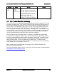
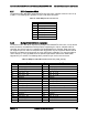
Pin
Signal Name
Pin
Signal Name
9
LED_HDD_ACTIVITY_N
10
FP_LED_STATUS_AMBER_BUF_N
11
FP_PWR_BTN_N
12
LED_NIC_LINK0_ACT_BUF_N
13
GND
14
LED_NIC_LINK0_LNKUP_BUF_N
15
FP_RST_BTN_N
16
SMB_SENSOR_3V3STBY_DATA
17
GND
18
SMB_SENSOR_3V3STBY_CLK
19
FP_ID_BTN_N
20
FP_CHASSIS_INTRUSION
21
PU_FM_SIO_TEMP_SENSOR
22
LED_NIC_LINK1_ACT_BUF_N
23
FP_NMI_BTN_N
24
LED_NIC_LINK1_LNKUP_BUF_N
25
<Empty Pin>
26
<Empty Pin>
27
LED_NIC_LINK2_ACT_FP_N
28
LED_NIC_LINK3_ACT_FP_N
29
LED_NIC_LINK2_LNKUP_FP_N
30
LED_NIC_LINK3_LNKUP_FP_N
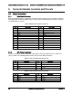
6.2.2 Front Panel USB Connector
The server board includes a 10-pin connector, that when cabled, can provide up to two USB
ports to a front panel. The following table provides the connector pin-out.
Table 35. Front Panel USB Connector Pin-out
Pin
Signal Name
Pin
Signal Name
1
P5V_USB_FP
2
P5V_USB_FP
3
USB2_P13_F_DN
4
USB2_P11_F_DN
5
USB2_P13_F_DP
6
USB2_P11_F_DP
7
GND
8
GND
9
KEY
10
NA
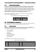
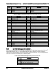
6.2.3 Local Control Panel Connector
The server board includes a 7-pin connector that is used when the system is configured with the
Intel Local Control Panel with LCD support. The following table provides the pin-out for this
connector.
Table 36. Local Front Panel Connector Pin-out
Pin
Signal Name
Pin
Signal Name
1
SMB_SENSOR_3V3STBY_DATA
2
GND
3
SMB_SENSOR_3V3STBY_CLK
4
P3V3_AUX
5
FM_LCP_ENTER_N
6
FM_LCP_LEFT_N
7
FM_LCP_RIGHT_N
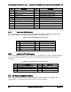
6.3 On Board Storage Connectors
The server board provides connectors for support of several storage device options. This
section provides a functional overview and pin-out of each connector.