
Technical Product Specification

Connector/Header Locations and Pin-outs Intel® Server Board S2600IP and Intel® Workstation Board W2600CR TPS
92 Intel order number G34153-004 Revision 1.4
6. Connector/Header Locations and Pin-outs
6.1 Power Connectors
6.1.1 Main Power Connector
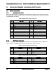
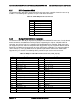
Main server board power is supplied by one 24-pin power connector. The connector is labeled
as “MAIN PWR” on the left bottom of the server board. The following tables provide the pin-out
for “MAIN PWR” connector.
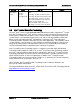
Table 30. Main Power Connector Pin-out
Pin
Signal Name
Pin
Signal Name
1
P3V3
13
P3V3
2
P3V3
14
N12V
3
GND
15
GND
4
P5V
16
FM_PS_EN_PSU_N
5
GND
17
GND
6
P5V
18
GND
7
GND
19
GND
8
PWRGD_PS_PWROK_PSU_R1
20
NC_PS_RES_TP
9
P5V_STBY_PSU
21
P5V
10
P12V
22
P5V
11
P12V
23
P5V
12
P3V3
24
GND
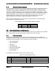
6.1.2 CPU Power Connectors
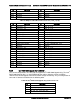
On the server board are two white 8-pin CPU power connectors labeled “CPU_1 PWR” and
“CPU_2 PWR”. The following table provides the pin-out for both connectors.
Table 31. CPU_1 Power Connector Pin-out
Pin
Signal Name
Pin
Signal Name
1
GND
5
P12V1
2
GND
6
P12V1
3
GND
7
P12V3A
4
GND
8
P12V3A
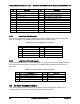
Table 32. CPU_2 Power Connector Pin-out
Pin
Signal Name
Pin
Signal Name
1
GND
5
P12V2
2
GND
6
P12V2
3
GND
7
P12V3B
4
GND
8
P12V3B