
Technical Product Specification

Intel® Server System P4000IP and Intel® Workstation System P4000CR Family TPS Thermal Management
78 Intel order number G38159-002 Revision 1.2
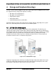
3. Thermal Management
The Intel
®
Server System P4000IP and Intel
®
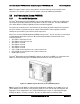
Workstation System P4000CR is designed to
operate at external ambient temperatures in compliance with ASHARE class A2. Working with
integrated platform management, features within the system are designed to move air in a front
to back direction, through the system and over critical components in order to prevent
overheating and allow the system to operate with best performance.
3.1 Thermal Operation and Configuration Requirements
To keep the system operating within supported maximum thermal limits, the system must meet
the following operating and configuration guidelines:
The system operating ambient is designed for sustained operation up to 35ºC (ASHRAE
Class A2) with short term excursion based operation up to 45ºC (ASHRAE Class A4).
o The system can operate up to 40ºC (ASHRAE Class A3) for up to 900 hours per
year
o The system can operate up to 45ºC (ASHRAE Class A4) for up to 90 hours per
year
o System performance may be impacted when operating within the extended
operating temperature range
o There is no long term system reliability impact when operating at the extended
temperature range within the approved limits.
Specific configuration requirements and limitations are documented in the configuration
matrix found in the Intel
®
Server System R2000IP product family Power Budget and
Thermal Configuration Guidelines Tool, available as a download online at Intel.com.
The CPU-1 processor + CPU heat sink must be installed first. The CPU-2 heat sink must
be installed at all times, with or without a processor installed.
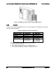
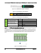
Memory Slot population requirements –
Note: Specified memory slots can be populated with a DIMM or supplied DIMM Blank.
Memory population rules apply when installing DIMMs.
o DIMM Population Rules on CPU-1 – Install DIMMs in order; Channels A, B, C,
and D. Start with1st DIMM (Blue Slot) on each channel, then slot 2. Only remove
factory installed DIMM blanks when populating the slot with memory.
o DIMM Population on CPU-2 – Install DIMMs in order; Channels E, F, G, and H.
Start with first DIMM (Blue Slot) on each channel, and then slot 2. Remove
onlyfactory installed DIMM blanks when populating the slot with memory.
All hard drive bays must be populated. Hard drive carriers can be populated with a hard
drive or supplied drive blank.
With the system operating, the air duct must be installed at all times.
In single power supply configurations, the second power supply bay must have the supplied
filler blank installed at all times.
The system must be configured with dual power supplies for the system to support fan
redundancy.
Thermally, the system can support the following PCI add-in cards.
o Add-in cards with a minimum 100 LFM (0.5 m/s) air flow requirement can be
installed in any available add-in card slot
o Add-in cards with a minimum 200 LFM (1 m/s) air flow requirement can be
installed in any available add-in card slot.