
Technical Product Specification


Intel® Server System P4000IP and Intel® Workstation System P4000CR Family TPS System Power Sub-system
76 Intel order number G38159-002 Revision 1.2
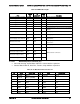
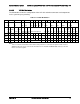
Table 90. PDB Over Current Protection Limits/240VA Protection
Output Voltage
Min OCP Trip Limits
Max OCP Trip Limits
Usage
+3.3V
27A
Meet 240VA
PCIe, Misc
+5V
27A
PCIe, HDD, Misc
+12V1
91A
100A
CPU and memory
+12V2
76A
100A
GPU cards
+12V3
18A
20A
HDD and peripherals
+12V4
18A
20A
HDD and peripherals
2.4.3.2 Over Voltage Protection (OVP)
Each DC/DC converter output on PDB have individual OVP protection circuits built in and it
shall be locally sensed. The PS+PDB combo shall shutdown and latch off after an over voltage
condition occurs. This latch shall be cleared by toggling the PSON
#
signal or by an AC power
interruption. Table 135 contains the over voltage limits. The values are measured at the PDB
harness connectors. The voltage shall never exceed the maximum levels when measured at the
power pins of the output harness connector during any single point of fail. The voltage shall
never trip any lower than the minimum levels when measured at the power pins of the PDB
connector.
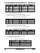
Table 91. Over Voltage Protection (OVP) Limits
Output voltage
OVP min (v)
OVP max (v)
+3.3V
3.9
4.8
+5V
5.7
6.5
+5VSB
5.7
6.5
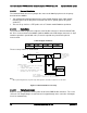
2.4.4 PWOK (Power OK) Signal
The PDB connects the PWOK signals from the power supply modules and the DC/DC
converters to a common PWOK signal. This common PWOK signal connects to the PWOK pin
on P1. The DC/DC convert PWOK signals have open collector outputs.
2.4.4.1 System PWOK requirements
The system will connect the PWOK signal to 3.3V or 5V from a pull-up resistor. The maximum
sink current of the power supplies are 0.5mA. The minimum resistance of the pull-up resistor is
stated below depending upon the motherboard’s pull-up voltage. Refer to the CRPS Power
Supply Specification for signal details.
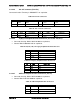
Table 92. System PWOK Requirements
Motherboard pull-up voltage
MIN resistance value (ohms)
5V
10K
3.3V
6.8K
2.4.5 PSON Signal
The PDB connects the power supplies PSON signals together and connect them to the PSON
signal on P1.
Refer to the CRPS power supply specification for signal details.