
Technical Product Specification


System Power Sub-system Intel® Server System P4000IP and Intel® Workstation System P4000CR Family TPS
Revision 1.2 Intel order number G38159-002
71
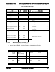
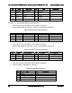
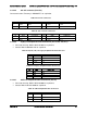
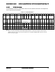
2.4.2.5 12V Rail Distribution
The below table shows the configuration of the 12V rails and what connectors and components
in the system they are powering.
Table 81. 12V Rail Distribution
P2
P3
P12
P1
P8
P9
P10
P11
P5,6,7
P13
P14
P15
P16
P17
P18
P19
P20
2x4
2x4
2x2
2x12
1x4
1x4
1x4
1x4
(2)
1x5,
1x4
GPU1
GPU2
GPU3
GPU4
OCP
CPU
1
Memo
ry1
CPU2
Memo
ry2
PCIe
Fans
Misc
HDD and peripherals
2x3
2x4
2x3
2x4
2x3
2x4
2x3
2x4
Total
Curr
ent
Min
Nom
inal
Max
12V1
17.8
A
10.5 A
17.8 A
10.5 A
21.7
A
10.0
A
3.0
A
91 A
91
95.5
100
12V2
6.3
A
12.5
A
6.3
A
12.5
A
6.3
A
12.5
A
6.3
A
12.5
A
76 A
76
88
100
12V3
18.0 A
18 A
18
19
20
12V4
18.0A
18A
18
19
20
Note:
P12 is reserved for board that needs 4 x GPU cards powered. P1 is the main 12V power for PCIe slot; but
additional 12V power can be connected to P2 and/or P3. The motherboard MUST NOT short any of the 12V
rails or connectors together.