
Technical Product Specification


Intel® Server System P4000IP and Intel® Workstation System P4000CR Family TPS System Power Sub-system
44 Intel order number G38159-002 Revision 1.2
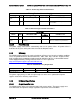
2.2.4.10 Hot Swap Requirements
Hot swapping a power supply is the process of inserting and extracting a power supply from an
operating power system. During this process the output voltages shall remain within the limits
with the capacitive load specified. The hot swap test must be conducted when the system is
operating under static, dynamic, and zero loading conditions. The power supply shall use a
latching mechanism to prevent insertion and extraction of the power supply when the AC power
cord is inserted into the power supply.
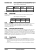
2.2.4.11 Forced Load Sharing
The +12V output will have active load sharing. The output will share within 10% at full load. The
failure of a power supply should not affect the load sharing or output voltages of the other
supplies still operating. The supplies must be able to load share in parallel and operate in a hot-
swap/redundant 1+1 configurations. The 12VSBoutput is not required to actively share current
between power supplies (passive sharing). The 12VSBoutput of the power supplies are
connected together in the system so that a failure or hot swap of a redundant power supply
does not cause these outputs to go out of regulation in the system.
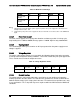
2.2.4.12 Ripple/Noise
The maximum allowed ripple/noise output of the power supply is defined in the table below.
This is measured over a bandwidth of 10Hz to 20MHz at the power supply output connectors. A
10F tantalum capacitor in parallel with a 0.1F ceramic capacitor is placed at the point of
measurement.
Table 39. Ripples and Noise
+12V main
+12VSB
120mVp-p
120mVp-p
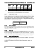
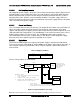
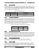
The test set-up shall be as shown below:
AC HOT
POWER SUPPLY
AC NEUTRAL
V
OUT
RETURN
V
AC GROUND
LOAD
SCOPE
LOAD MUST BE
ISOLATED FROM
THE GROUND OF
THE POWER
SUPPLY
10uF
.1uF
GENERAL NOTES:
1. LOAD THE OUTPUT WITH ITS MINIMUM
LOAD CURRENT.
2. CONNECT THE PROBES AS SHOWN.
3. REPEAT THE MEASUREMENTS WITH THE
MAXIMUM LOAD ON THE OUTPUT.
SCOPE NOTE:
USE A TEKTRONIX 7834 OSCILLOSCOPE WITH 7A13 AND
DIFFERENTIAL PROBE P6055 OR EQUIVALENT.
Figure 21. Differential Noise test setup
Note: When performing this test, the probe clips and capacitors should be located close to the load.