
Technical Product Specification


Intel® Server System P4000IP and Intel® Workstation System P4000CR Family TPS System Power Sub-system
28 Intel order number G38159-002 Revision 1.2
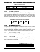
2.1.3 Efficiency
The following table provides the required minimum efficiency level at various loading conditions.
These are provided at three different load levels; 100%, 50%, 20%, and 10%. Output shall be
load according to the proportional loading method defined by 80 Plus in Generalized Internal
Power Supply Efficiency Testing Protocol, Rev. 6.4.3. This is posted at
http://efficientpowersupplies.epri.com/methods.asp.
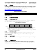
Table 15. Silver Efficiency Requirement
Loading
100% of maximum
50% of maximum
20% of maximum
10% of maximum
Minimum Efficiency
91%
94%
90%
82%
The power supply passes with enough margins to make sure in production all power supplies meet these
efficiency requirements.
2.1.4 DC Output Specification
2.1.4.1 Output Power/Currents
The following table defines the minimum power and current ratings. The power supply meets
both static and dynamic voltage regulation requirements for all conditions.
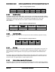
Table 16. Minimum Load Ratings
Parameter
Min
Max.
Peak 2, 3
Unit
12V main
0.0
62.0
70.0
A
12Vstby 1
0.0
2.1
2.4
A
Notes:
1. 12Vstby must provide 4.0A with two power supplies in parallel. The Fan may work when stby current
>1.5A
2. Length of time peak power can be supported is based on thermal sensor and assertion of the
SMBAlert# signal. Minimum peak power duration shall be 20 seconds without asserting the SMBAlert#
signal at maximum operating temperature.
2.1.4.2 Pmax Power support
The PSU should support 3msec peak power duration at a 50msec period; 5.7% duty cycle,
Step loading from 730W to 1050W, Average power = 750W. Full AC input range; 100-
127VAC/200-240VAC
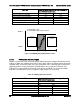
2.1.4.3 Standby Output
The 12VSB output is present when an AC input greater than the power supply turn on voltage is
applied.
2.1.4.4 Voltage Regulation
The power supply output voltages stay within the following voltage limits when operating at
steady state and dynamic loading conditions. These limits include the peak-peak ripple/noise.
These shall be measured at the output connectors.