
Technical Product Specification

Intel® Server System R2000IP Product Family TPS System Storage and Peripheral Drive Bays
Revision 1.1
47
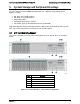
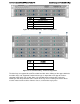
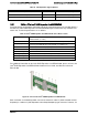
Figure 34. 3.5” Drive Hot-Swap Backplane Overview
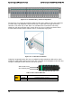
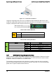
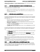
Behind each backplane are several connectors. The following illustration identifies these
connectors.
Label
Description
A
Power connector
B
4-port mini-SAS connectors
C
SMBus* connector
Figure 35. 3.5” Hard Drive Backplane backside
A – Power Harness Connector - The backplane includes a 2x2 connector supplying power to
the backplane. Power is routed to the backplane from a power cable harness from the server
board
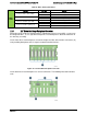
B – 4-port Mini-SAS Connectors – The backplane includes two or three multi-port mini-SAS
cable connectors, each providing I/O signals for four SAS/SATA hard drives on the backplane.
Cables can be routed from matching connectors on the server board, add-in SAS/SATA RAID
cards, or optionally installed SAS expander cards. Each mini-SAS connector will include a silk-
screen identifying which drives the connector supports; Drives 0-3, Drives 4-7, and Drives 8-11.
C – SMBus* Cable Connectors – The backplane includes a 1x5 cable connector used as a
management interface to the server board.
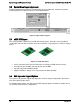
5.2.2 Cypress* CY8C22545 Enclosure Management Controller
The backplanes support enclosure management using a Cypress* CY8C22545 Programmable
System-on-Chip (PSoC*) device.
The CY8C22545 drives the hard drive activity/fault LED, hard
drive present signal, and controls hard drive power-up during system power-on.