
Technical Product Specification

Intel® Server System R2000IP Product Family TPS System Storage and Peripheral Drive Bays
Revision 1.1
43
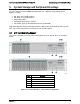
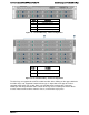
Table 38. Drive Activity LED States
Green
Condition
Drive Type
Behavior
Power on with no drive activity
SAS
LED stays on
SATA
LED stays off
Power on with drive activity
SAS
LED blinks off when processing a command
SATA
LED blinks on when processing a command
Power on and drive spun down
SAS
LED stays off
SATA
LED stays off
Power on and drive spinning up
SAS
LED blinks
SATA
LED stays off
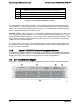
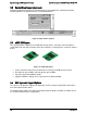
5.1.1 2.5” Drive Hot-Swap Backplane Overview
Depending on the number of hard disk drives supported by a given system SKU, a system can
be configured with 1, 2, or 3 eight drive backplanes. Each backplane is attached to the back of
the drive bay assembly.
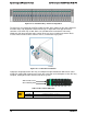
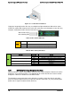
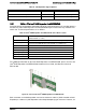
On the front side of each backplane are mounted eight hard disk drive interface connectors (A),
each providing both power and I/O signals to attached hard disk drives.
Figure 29. 2.5" Hard Drive Backplane front side
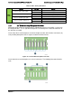
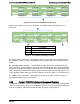
On the backside of each backplane are several connectors. The following illustration identifies
each.