
Technical Product Specification


Intel® Server System R2000IP Product Family TPS Power Subsystem
Revision 1.1
25
stability with local sensing through the submission of Bode plots. Closed-loop stability must be
ensured at the maximum and minimum loads as applicable.
3.6.11 Common Mode Noise
The Common Mode noise on any output shall not exceed 350mV pk-pk over the frequency
band of 10Hz to 20MHz.
1. The measurement shall be made across a 100Ω resistor between each of DC outputs,
including ground at the DC power connector and chassis ground (power subsystem
enclosure).
2. The test set-up shall use a FET probe such as Tektronix model P6046 or equivalent.
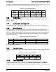
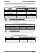
3.6.12 Ripple/Noise
The maximum allowed ripple/noise output of the power supply is defined in table below. This is
measured over a bandwidth of 0Hz to 20MHz at the power supply output connectors. A 10F
tantalum capacitor in parallel with a 0.1F ceramic capacitor are placed at the point of
measurement.
Table 20. Ripple and Noise
Output
+12V Output
+5Vsb Output
Ripple/Noise
120mVp-p
50mVp-p
Note: When performing this test, the probe clips and capacitors should be located close to the load.
3.6.13 Soft Starting
The Power Supply shall contain control circuit which provides monotonic soft start for its outputs
without overstress of the AC line or any power supply components at any specified DC input or
load conditions. There is no requirement for rise time on the 5Vstby but the turn on/off shall be
monotonic.
3.6.14 Zero Load Stability Requirements
When the power subsystem operates in a no load condition on all outputs including 5VSB in a
1+0 or 1+1 configuration, it does not need to meet the output regulation specification, but it must
operate without any tripping of over-voltage or other fault circuitry. When the power subsystem
is subsequently loaded, it must begin to regulate and source current without fault.
3.6.15 Hot Swap Requirements
Hot swapping a power supply is the process of inserting and extracting a power supply from an
operating power system. During this process the output voltages shall remain within the limits
with the capacitive load specified. The hot swap test must be conducted when the system is
operating under static, dynamic, and zero loading conditions. The power supply can be hot
swapped by the following method:
Extraction: The AC power will be disconnected from the power supply before the power supply
is being extracted from the system. This could occur in standby mode or powered on mode.
Insertion: The AC power will be connected to the power supply after the supply is inserted into
the system and the supply will power on into standby mode or powered on mode.