
S2600GZ and S2600GL


Table Of Contents
- 1. Introduction
- 2. Product Overview
- 3. Product Architecture Overview
- 3.1 Processor Support
- 3.2 Processor Functions Overview
- 3.2.1 Processor Core Features:
- 3.2.2 Supported Technologies:
- 3.2.3 Intel® QuickPath Interconnect
- 3.2.4 Integrated Memory Controller (IMC) and Memory Subsystem
- 3.2.4.1 Supported Memory
- 3.2.4.2 Memory Slot Identification and Population Rules
- 3.2.4.3 Publishing System Memory
- 3.2.4.4 Integrated Memory Controller Operating Modes
- 3.2.4.5 Memory RAS Support
- 3.2.5 Processor Integrated I/O Module (IIO)
- 3.3 Intel® C602 Chipset Functional Overview
- 3.4 Integrated Baseboard Management Controller Overview
- 4. System Security
- 5. Technology Support
- 6. Platform Management Functional Overview
- 6.1 Baseboard Management Controller (BMC) Firmware Feature Support
- 6.2 Advanced Configuration and Power Interface (ACPI)
- 6.3 Power Control Sources
- 6.4 BMC Watchdog
- 6.5 Fault Resilient Booting (FRB)
- 6.6 Sensor Monitoring
- 6.7 Field Replaceable Unit (FRU) Inventory Device
- 6.8 System Event Log (SEL)
- 6.9 System Fan Management
- 6.10 Messaging Interfaces
- 6.10.1 User Model
- 6.10.2 IPMB Communication Interface
- 6.10.3 LAN Interface
- 6.10.4 Address Resolution Protocol (ARP)
- 6.10.5 Internet Control Message Protocol (ICMP)
- 6.10.6 Virtual Local Area Network (VLAN)
- 6.10.7 Secure Shell (SSH)
- 6.10.8 Serial-over-LAN (SOL 2.0)
- 6.10.9 Platform Event Filter (PEF)
- 6.10.10 LAN Alerting
- 6.10.11 Alert Policy Table
- 6.10.12 SM-CLP (SM-CLP Lite)
- 6.10.13 Embedded Web Server
- 6.10.14 Virtual Front Panel
- 6.10.15 Embedded Platform Debug
- 6.10.16 Data Center Management Interface (DCMI)
- 6.10.17 Lightweight Directory Authentication Protocol (LDAP)
- 7. Advanced Management Feature Support (RMM4)
- 8. On-board Connector/Header Overview
- 9. Reset and Recovery Jumpers
- 10. Light Guided Diagnostics
- 11. Power Supply Specification Guidelines
- 11.1 Power Supply DC Output Connector
- 11.2 Power Supply DC Output Specification
- 11.2.1 Output Power/Currents
- 11.2.2 Standby Output
- 11.2.3 Voltage Regulation
- 11.2.4 Dynamic Loading
- 11.2.5 Capacitive Loading
- 11.2.6 Grounding
- 11.2.7 Closed loop stability
- 11.2.8 Residual Voltage Immunity in Standby mode
- 11.2.9 Common Mode Noise
- 11.2.10 Soft Starting
- 11.2.11 Zero Load Stability Requirements
- 11.2.12 Hot Swap Requirements
- 11.2.13 Forced Load Sharing
- 11.2.14 Ripple/Noise
- 11.2.15 Timing Requirements
- 12. BIOS Setup Utility
- Table 60. BIOS Setup: Keyboard Command Bar
- Back to [Main Screen]
- Back to [Main Screen]
- Back to [Main Screen]
- Back to [Main Screen]
- Back to [Main Screen]
- Back to [Main Screen]
- Back to [Main Screen]
- Back to [Main Screen]
- Back to [Advanced Screen]
- Back to [Advanced Screen]
- Back to [Advanced Screen]
- Back to [Advanced Screen]
- Back to [Advanced Screen]
- Back to [Advanced Screen]
- Back to [Advanced Screen]
- Back to [Advanced Screen]
- Screen Field Descriptions:
- Back to [Processor Configuration Screen] — [Advanced Screen]
- Back to [Processor Configuration Screen] — [Advanced Screen]
- Back to [Processor Configuration Screen] — [Advanced Screen]
- Back to [Processor Configuration Screen] — [Advanced Screen]
- Back to [Processor Configuration Screen] — [Advanced Screen]
- Back to [Processor Configuration Screen] — [Advanced Screen]
- Back to [Processor Configuration Screen] — [Advanced Screen]
- Back to [Processor Configuration Screen] — [Advanced Screen]
- Back to [Processor Configuration Screen] — [Advanced Screen]
- Back to [Processor Configuration Screen] — [Advanced Screen]
- Back to [Processor Configuration Screen] — [Advanced Screen]
- Back to [Processor Configuration Screen] — [Advanced Screen]
- Back to [Processor Configuration Screen] — [Advanced Screen]
- Back to [Processor Configuration Screen] — [Advanced Screen]
- Back to [Processor Configuration Screen] — [Advanced Screen]
- Back to [Processor Configuration Screen] — [Advanced Screen]
- Back to [Processor Configuration Screen] — [Advanced Screen]
- Back to [Processor Configuration Screen] — [Advanced Screen]
- Back to [Processor Configuration Screen] — [Advanced Screen]
- Back to [Processor Configuration Screen] — [Advanced Screen]
- Back to [Processor Configuration Screen] — [Advanced Screen]
- Back to [Processor Configuration Screen] — [Advanced Screen]
- Back to [Processor Configuration Screen] — [Advanced Screen]
- Back to [Processor Configuration Screen] — [Advanced Screen]
- Back to [Processor Configuration Screen] — [Advanced Screen]
- Back to [Processor Configuration Screen] — [Advanced Screen]
- Back to [Processor Configuration Screen] — [Advanced Screen]
- Back to Processor Configuration Screen] — [Advanced Screen]
- Back to [Processor Configuration Screen] — [Advanced Screen]
- Back to [Processor Configuration Screen] — [Advanced Screen]
- Back to [Processor Configuration Screen] — [Advanced Screen]
- Back to [Processor Configuration Screen] — [Advanced Screen]
- Back to [Processor Configuration Screen] — [Advanced Screen]
- Figure 44. Power & Performance Screen
- Back to [Power & Performance Screen] — [Advanced Screen]
- Figure 45. Memory Configuration Screen
- Back to [Memory Configuration Screen] — [Advanced Screen]
- Back to [Memory Configuration Screen] — [Advanced Screen]
- Back to [Memory Configuration Screen] — [Advanced Screen]
- Back to [Memory Configuration Screen] — [Advanced Screen]
- Back to [Memory Configuration Screen] — [Advanced Screen]
- Back to [Memory Configuration Screen] — [Advanced Screen]
- Back to [Memory Configuration Screen] — [Advanced Screen]
- Back to [Memory Configuration Screen] — [Advanced Screen]
- Back to [Memory Configuration Screen] — [Advanced Screen]
- Back to [Memory Configuration Screen] — [Advanced Screen]
- Back to [Memory Configuration Screen] — [Advanced Screen]
- Back to [Memory Configuration Screen] — [Advanced Screen]
- Back to [Memory Configuration Screen] — [Advanced Screen]
- Figure 46. Memory RAS and Performance Configuration Screen
- Figure 47. Mass Storage Controller Configuration Screen
- Screen Field Descriptions:
- One of these strings:
- Back to [Mass Storage Controller Configuration Screen]
- One of these strings:
- Back to [Mass Storage Controller Configuration Screen]
- Back to [Mass Storage Controller Configuration Screen]
- Back to [Mass Storage Controller Configuration Screen]
- Back to [Mass Storage Controller Configuration Screen]
- Back to [Mass Storage Controller Configuration Screen]
- Back to [Mass Storage Controller Configuration Screen]
- Back to [Mass Storage Controller Configuration Screen]
- Names of Storage Modules supported at this time are:
- Back to [Mass Storage Controller Configuration Screen]
- Back to [Mass Storage Controller Configuration Screen]
- Figure 48. PCI Configuration Screen
- Back to [PCI Configuration Screen] — [Advanced Screen]
- Back to [PCI Configuration Screen] — [Advanced Screen]
- Back to [PCI Configuration Screen] — [Advanced Screen]
- Back to [PCI Configuration Screen] — [Advanced Screen]
- Back to [PCI Configuration Screen] — [Advanced Screen]
- Back to [PCI Configuration Screen] — [Advanced Screen]
- Back to [PCI Configuration Screen] — [Advanced Screen]
- Figure 49. NIC Configuration Screen
- One of these strings:
- One of these strings:
- Figure 50. Serial Port Configuration Screen
- Back to [Serial Port Configuration Screen]
- Back to [Serial Port Configuration Screen]
- Back to [Serial Port Configuration Screen]
- Back to [Serial Port Configuration Screen]
- Back to [Serial Port Configuration Screen]
- Back to [Serial Port Configuration Screen]
- Figure 51. USB Configuration Screen
- Back to [USB Configuration Screen]
- Back to [USB Configuration Screen]
- Back to [USB Configuration Screen]
- Back to [USB Configuration Screen]
- Back to [USB Configuration Screen]
- Back to [USB Configuration Screen]
- Back to [USB Configuration Screen]
- Figure 52. System Acoustic and Performance Configuration
- Back to [System Acoustic and Performance Configuration]
- Back to [System Acoustic and Performance Configuration]
- Back to [System Acoustic and Performance Configuration]
- Back to [System Acoustic and Performance Configuration]
- Back to [System Acoustic and Performance Configuration]
- Figure 53. Security Screen
- Back to [Security Screen]
- Back to [Security Screen]
- Back to [Security Screen]
- Back to [Security Screen]
- Back to [Security Screen]
- Back to [Security Screen]
- Back to [Security Screen]
- Back to [Security Screen]
- Figure 54. Server Management Screen
- Back to [Server Management Screen]
- Back to [Server Management Screen]
- Back to [Server Management Screen]
- Back to [Server Management Screen]
- Back to [Server Management Screen]
- Back to [Server Management Screen]
- Back to [Server Management Screen]
- Back to [Server Management Screen]
- Back to [Server Management Screen]
- Back to [Server Management Screen]
- Back to [Server Management Screen]
- Back to [Server Management Screen]
- Back to [Server Management Screen]
- Back to [Server Management Screen]
- Back to [Server Management Screen]
- Back to [Server Management Screen]
- Back to [Server Management Screen]
- Back to [Server Management Screen]
- Back to [Server Management Screen]
- Back to [Server Management Screen]
- Figure 55. Console Redirection Screen
- Back to [Console Redirection Screen] — [Server Management Screen]
- Back to [Console Redirection Screen] — [Server Management Screen]
- Back to [Console Redirection Screen] — [Server Management Screen]
- Back to [Console Redirection Screen] — [Server Management Screen]
- Back to [Console Redirection Screen] — [Server Management Screen]
- Back to [Console Redirection Screen] — [Server Management Screen]
- Figure 56. System Information Screen
- Back to [System Information Screen] — [Server Management Screen]
- Back to [System Information Screen] — [Server Management Screen]
- Back to [System Information Screen] — [Server Management Screen]
- Back to [System Information Screen] — [Server Management Screen]
- Back to [System Information Screen] — [Server Management Screen]
- Back to [System Information Screen] — [Server Management Screen]
- Back to [System Information Screen] — [Server Management Screen]
- Back to [System Information Screen] — [Server Management Screen]
- Back to [System Information Screen] — [Server Management Screen]
- Back to [System Information Screen] — [Server Management Screen]
- Back to [System Information Screen] — [Server Management Screen]
- Figure 57. BMC LAN Configuration Screen
- Back to [BMC LAN Configuration Screen] — [Server Management Screen]
- Option Values: [Entry Field 0.0.0.0, 0.0.0.0 is default]
- Back to [BMC LAN Configuration Screen] — [Server Management Screen]
- Option Values: [Entry Field 0.0.0.0, 0.0.0.0 is default]
- Back to [BMC LAN Configuration Screen] — [Server Management Screen]
- Option Values: [Entry Field 0.0.0.0, 0.0.0.0 is default]
- Back to [BMC LAN Configuration Screen] — [Server Management Screen]
- Back to [BMC LAN Configuration Screen] — [Server Management Screen]
- Back to [BMC LAN Configuration Screen] — [Server Management Screen]
- Back to [BMC LAN Configuration Screen] — [Server Management Screen]
- Back to [BMC LAN Configuration Screen] — [Server Management Screen]
- Back to [BMC LAN Configuration Screen] — [Server Management Screen]
- Back to [BMC LAN Configuration Screen] — [Server Management Screen]
- Back to [BMC LAN Configuration Screen] — [Server Management Screen]
- Option Values: [Entry Field 0.0.0.0, 0.0.0.0 is default]
- Back to [BMC LAN Configuration Screen] — [Server Management Screen]
- Option Values: [Entry Field 0.0.0.0, 0.0.0.0 is default]
- Back to [BMC LAN Configuration Screen] — [Server Management Screen]
- Option Values: [Entry Field 0.0.0.0, 0.0.0.0 is default]
- Back to [BMC LAN Configuration Screen] — [Server Management Screen]
- Back to [BMC LAN Configuration Screen] — [Server Management Screen]
- Back to [BMC LAN Configuration Screen] — [Server Management Screen]
- Back to [BMC LAN Configuration Screen] — [Server Management Screen]
- Back to [BMC LAN Configuration Screen] — [Server Management Screen]
- Back to [BMC LAN Configuration Screen] — [Server Management Screen]
- Back to [BMC LAN Configuration Screen] — [Server Management Screen]
- Back to [BMC LAN Configuration Screen] — [Server Management Screen]
- Back to [BMC LAN Configuration Screen] — [Server Management Screen]
- Back to [BMC LAN Configuration Screen] — [Server Management Screen]
- Back to [BMC LAN Configuration Screen] — [Server Management Screen]
- Figure 58. Boot Options Screen
- Back to [Boot Options Screen]
- Back to [Boot Options Screen]
- Back to [Boot Options Screen]
- Back to [Boot Options Screen]
- Back to [Boot Options Screen]
- Back to [Boot Options Screen]
- Back to [Boot Options Screen]
- Back to [Boot Options Screen]
- Back to [Boot Options Screen]
- Back to [Boot Options Screen]
- Back to [Boot Options Screen]
- Back to [Boot Options Screen]
- Back to [Boot Options Screen]
- Back to [Boot Options Screen]
- Back to [Boot Options Screen]
- Back to [Boot Options Screen]
- Figure 59. CDROM Order Screen
- Back to [CDROM Order Screen] — [Boot Options Screen]
- Figure 60. Hard Disk Order Screen
- Back to [Hard Disk Order Screen] — [Boot Options Screen]
- Figure 61. Floppy Order Screen
- Back to [Floppy Order Screen] — [Boot Options Screen]
- Figure 62. Network Device Order Screen
- Back to [Network Device Order Screen] — [Boot Options Screen]
- Figure 63. BEV Device Order Screen
- Back to [BEV Device Order Screen] — [Boot Options Screen]
- Figure 64. Add EFI Boot Option Screen
- Figure 65. Delete EFI Boot Option Screen
- Figure 66. Boot Manager Screen
- Back to [Boot Manager Screen]
- Back to [Boot Manager Screen]
- Figure 67. Error Manager Screen
- Back to [Error Manager Screen]
- Back to [Error Manager Screen]
- Back to [Error Manager Screen]
- Back to [Error Manager Screen]
- Figure 68. Save & Exit Screen
- Back to [Save & Exit Screen]
- Back to [Save & Exit Screen]
- Back to [Save & Exit Screen]
- Back to [Save & Exit Screen]
- Back to [Save & Exit Screen]
- Back to [Save & Exit Screen]
- Back to [Save & Exit Screen]
- Appendix A: Integration and Usage Tips
- Appendix B: Integrated BMC Sensor Tables
- Appendix C: Management Engine Generated SEL Event Messages
- Appendix D: POST Code Diagnostic LED Decoder
- Appendix E: POST Code Errors
- Appendix F: Supported Intel® Server Systems
Product Architecture Overview Intel® Server Board S2600GZ/GL TPS
3.2.5.4
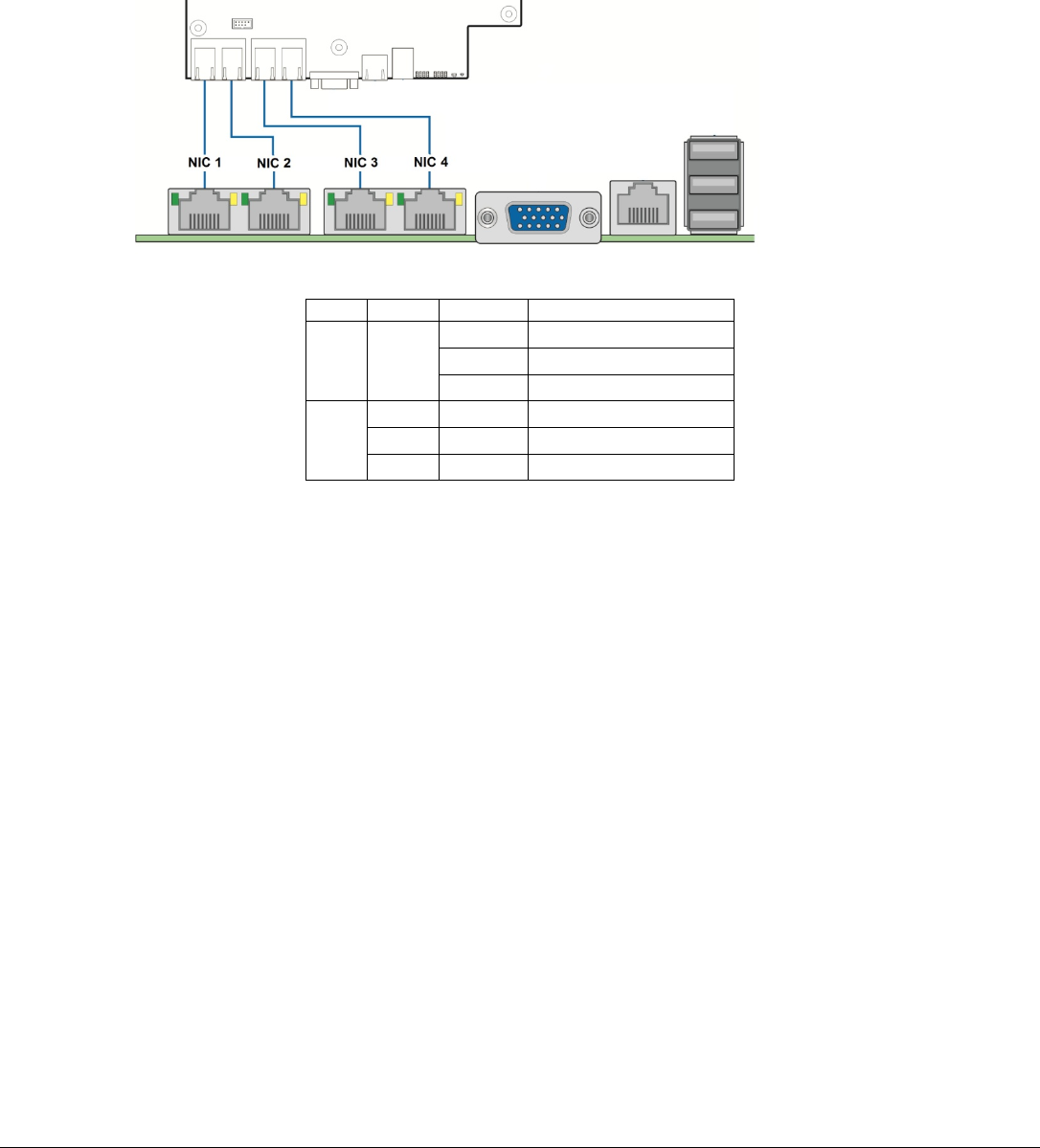
Network Interface
On-board network connectivity is provided by means of an Intel
®
Ethernet Controller I350-AM4 providing up to
four 10/100/1000 Mb Ethernet ports. The NIC chip is supported by x4 PCIe Gen2 signals from the IIO module
of the CPU 1 processor.
Each Ethernet port drives two LEDs located on each network interface connector. The LED at the right of the
connector is the link/activity LED and indicates network connection when on, and transmit/receive activity when
blinking. The LED at the left of the connector indicates link speed as defined in the following table:
LED
Color
LED State
NIC State
Left Green
Off
LAN link not established
On
LAN link is established
Blinking
LAN activity is occurring
Right
Off
10 Mb/sec data rate
Amber
On
100 Mb/sec data rate
Green
On
1000 Mb /sec data rate
Figure 23. Intel
®
Server Board S2600GZ/GL External RJ45 NIC Port LED Definition
The server board has seven MAC addresses programmed at the factory. MAC addresses are assigned as
follows:
NIC 1 MAC address (for OS usage)
NIC 2 MAC address = NIC 1 MAC address + 1 (for OS usage)
NIC 3 MAC address = NIC 1 MAC address + 2 (for OS usage)
NIC 4 MAC address = NIC 1 MAC address + 3 (for OS usage)
BMC LAN channel 1 MAC address = NIC1 MAC address + 4
BMC LAN channel 2 MAC address = NIC1 MAC address + 5
BMC LAN channel 3 (RMM) MAC address = NIC1 MAC address + 6
The printed MAC address on the server board and/or server system is assigned to NIC1 on the server board.
3.2.5.5
I/O Module Support
To broaden the standard on-board feature set, the server board provides support for one of several available
IO Module options. The I/O module attaches to a high density 80-pin connector on the server board (J2B1)
labeled “IO_Module” and is supported by x8 PCIe Gen3 signals from the IIO module of the CPU 1 processor.
Revision 2.4
38