
R2000GZ and R2000GL


Intel
®
Server System R2000GZ/GL Product Family TPS
BIOS Setup (BIOS>Advanced>System Acoustic and Performance Configuration) allow for parameter
adjustments based on the actual system configuration and usage. Refer to the following sections for a
description of each setting.
4.2.1 Set Throttling Mode
This option is used to select the desired memory thermal throttling mechanism. Available settings include:
[Auto], [DCLTT], [SCLTT] and [SOLTT].
[Auto] – Factory Default Setting - BIOS automatically detects and identifies the appropriate thermal throttling
mechanism based on DIMM type, airflow input, and DIMM sensor availability.
[DCLTT] – Dynamic Closed Loop Thermal Throttling: for the SOD DIMM with system airflow input
[SCLTT] – Static Close Loop Thermal Throttling: for the SOD DIMM without system airflow input
[SOLTT] – Static Open Loop Thermal Throttling: for the DIMMs without sensor on dimm (SOD)
4.2.2 Altitude
This option sets the proper altitude that the system will be used. Available settings include: [300m or less],
[301m-900m], [901m-1500m], [Above 1500m].
Selecting an altitude range that is lower than the actual altitude the system will be operating at, can cause the
fan control system to operate less efficiently, leading to higher system thermals and lower system performance.
If the altitude range selected is higher than the actual altitude the system will be operating at, the fan control
system may provide better cooling but with higher acoustics and higher fan power consumption. If the altitude
is not known, selecting a higher altitude is recommended in order to provide sufficient cooling.
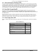
4.2.3 Set Fan Profile
This option sets the desired Fan Profile. Available settings include:
[Performance] and [Acoustic].
The Acoustic mode offers the best acoustic experience and appropriate cooling capability supporting the
majority of the add-in cards used. Performance mode is designed to provide sufficient cooling capability
covering all kinds of add-in cards on the market.
4.2.4 Fan PWM Offset
This option is reserved for manual adjustment to the minimum fan speed curves. The valid range is from [0 to
100] which stands for 0% to 100% PWM adding to the minimum fan speed. This feature is valid when Quiet
Fan Idle Mode is at Enabled state. The default setting is [0]
4.2.5 Quiet Fan Idle Mode
This feature can be [Enabled] or [Disabled]. If enabled, the fans will either shift to a lower speed or stop when
the aggregate sensor temperatures are satisfied, indicating the system is at ideal thermal/light loading
conditions. When the aggregate sensor temperatures are not satisfied, the fans will shift back to normal control
curves. If disabled, the fans will never shift into lower fan speeds or stop, regardless of whether the aggregate
sensor temperatures are satisfied or not. The default setting is [Disabled]
Note: The above feature may or may not be in effect and depends on the actual thermal characteristics of the
specified system.
4.2.6 Thermal Sensor Input for Fan Speed Control
The BMC uses various IPMI sensors as inputs to fan speed control. Some of the sensors are actual physical
sensors and some are “virtual” sensors derived from calculations.
Revision 2.2
33