
R2000GZ and R2000GL


Intel
®
Server System R2000GZ/GL Product Family TPS
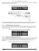
Each connector is labeled as “OPT_12V_PWR_1” and “OPT_12V_PWR_2” on the server board. The following
table provides the pin-out for both connectors.
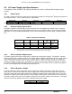
Table 4. Riser Slot Power Pin-out ("OPT_12V_PWR_#")
Signal Description
Pin#
Pin#
Signal Description
P12V
3
1
GROUND
P12V
4
2
GROUND
The power cable (as shown above) for the OPT_12V_PWR_# connector is included in the 2-slot Riser Card
accessory kit (A2UL16RISER ) and can support both 6 and 8 pin GPU card 12V AUX power connectors.
3.2.3 Hot Swap Backplane Power Connector
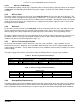
The server board includes one white 2x4-pin power connector that is cabled to provide power for hot swap
backplanes. On the server board, this connector is labeled as “HSBP PWR”. The following table provides the
pin-out for this connector.
Table 5. Hot Swap Backplane Power Connector Pin-out (“HSBP PWR")
Signal Description
Pin#
Pin#
Signal Description
P12V_240VA
5
1
GROUND
P12V_240VA
6
2
GROUND
P12V_240VA
7
3
GROUND
P12V_240VA
8
4
GROUND
3.2.4 Optical Drive and SSD Power Connector
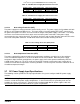
The server board includes one brown 2x3-pin power connector intended to provide power to optionally installed
optical drive and up to two Solid State Devices (SSDs) mounted to the top side of the air duct. On the server
board this connector is labeled as “ODD/SSD PWR”. The following table provides the pin-out for this
connector.
Table 6. Peripheral Drive Power Connector Pin-out (“ODD/SSD PWR”)
Signal Description
Pin#
Pin#
Signal Description
P12V
4
1
P5V
P3V3
5
2
P5V
GROUND
6
3
GROUND
Revision 2.2
19