
Technical Product Specification


Intel® Server Boards S4600LH2/T2 TPS
Revision 2.0
30
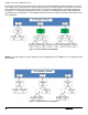
For RAS modes that require matching populations, the same slot positions across channels must hold the
same DIMM type with regards to size and organization. DIMM timings do not have to match but timings will be
set to support all DIMMs populated (i.e., DIMMs with slower timings will force faster DIMMs to the slower
common timing modes).
3.2.2.5.1 Single Device Data Correction (SDDC)
SDDC – Single Device Data Correction is a technique by which data can be replaced by the IMC from an
entire x4 DRAM device which is failing, using a combination of CRC plus parity. This is an automatic IMC
driven hardware. It can be extended to x8 DRAM technology by placing the system in Channel Lockstep Mode.
3.2.2.5.2 Error Correction Code (ECC) Memory
ECC uses “extra bits” – 64-bit data in a 72-bit DRAM array – to add an 8-bit calculated “Hamming Code” to
each 64 bits of data. This additional encoding enables the memory controller to detect and report single or
multiple bit errors when data is read, and to correct single-bit errors.
3.2.2.5.2.1 Correctable Memory ECC Error Handling
A “Correctable ECC Error” is one in which a single-bit error in memory contents is detected and corrected by
use of the ECC Hamming Code included in the memory data. For a correctable error, data integrity is
preserved, but it may be a warning sign of a true failure to come. Note that some correctable errors are
expected to occur.
The system BIOS has logic to cope with the random factor in correctable ECC errors. Rather than reporting
every correctable error that occurs, the BIOS has a threshold and only logs a correctable error when a
threshold value is reached. Additional correctable errors that occur after the threshold has been reached are
disregarded. In addition, on the expectation the server system may have extremely long operational runs
without being rebooted, there is a “Leaky Bucket” algorithm incorporated into the correctable error counting
and comparing mechanism. The “Leaky Bucket” algorithm reduces the correctable error count as a function of
time – as the system remains running for a certain amount of time, the correctable error count will “leak out” of
the counting registers. This prevents correctable error counts from building up over an extended runtime
The correctable memory error threshold value is a configurable option in the <F2> BIOS Setup Utility, where
you can configure it for 20/10/5/ALL/None
Once a correctable memory error threshold is reached, the event is logged to the System Event Log (SEL) and
the appropriate memory slot fault LED is lit to indicate on which DIMM the correctable error threshold crossing
occurred.
3.2.2.5.2.2 Uncorrectable Memory ECC Error Handling
All multi-bit “detectable but not correctable” memory errors are classified as Uncorrectable Memory ECC
Errors. This is generally a fatal error.
However, before returning control to the OS drivers via Machine Check Exception (MCE) or Non-Maskable
Interrupt (NMI), the Uncorrectable Memory ECC Error is logged to the SEL, the appropriate memory slot fault
LED is lit, and the System Status LED state is changed to a solid Amber.
3.2.2.5.3 Demand Scrubbing for ECC Memory
Demand scrubbing is the ability to write corrected data back to the memory once a correctable error is
detected on a read transaction. This allows for correction of data in memory at detect, and decrease the
chances of a second error on the same address accumulating to cause a multi-bit error (MBE) condition.
Demand Scrubbing is enabled/disabled (default is enabled) in the Memory Configuration screen in Setup.