
Technical Product Specification


Intel® Server Boards S4600LH2/T2 TPS
Revision 2.0
29
Lockstep channels must be populated identically. That is, each DIMM in one channel must have a
corresponding DIMM of identical organization (number ranks, number banks, number rows, and number
columns). DIMMs may be of different speed grades, but the iMC module will be configured to operate all
DIMMs according to the slowest parameters present by the Memory Reference Code (MRC).
Channel 0 and channel 1 can be in lockstep. Channel 2 and 3 can be in lockstep.
Performance in lockstep mode cannot be as high as with independent channels. The burst length for DDR3
DIMMs is eight which is shared between two channels that are in lockstep mode. Each channel of the pair
provides 32 bytes to produce the 64-byte cache-line. DRAMs on independent channels are configured to
deliver a burst length of eight. The maximum read bandwidth for a given Rank is half of peak. There is another
draw back in using lockstep mode, i.e. higher power consumption since the total activation power is about
twice of the independent channel operation if comparing to same type of DIMMs.
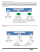
3.2.2.4.3 Mirror Mode
Memory mirroring mode is the mechanism by which a component of memory is mirrored. In mirrored mode,
when a write is performed to one copy, a write is generated to the target location as well. This guarantees that
the target is always updated with the latest data from the main copy. The iMC module supports mirroring
across the corresponding mirroring channel within the processor socket but not across sockets. DIMM
organization in each slot of one channel must be identical to the DIMM in the corresponding slot of the other
channel. This allows a single decode for both channels. When mirroring mode is enabled, memory image in
Channel 0 is maintained the same as Channel 1 and Channel 2 is maintained the same as Channel 3
3.2.2.5 Memory RAS Support
The server board supports the following memory RAS modes:
Single Device Data Correction (SDDC)
Error Correction Code (ECC) Memory
Demand Scrubbing for ECC Memory
Patrol Scrubbing for ECC Memory
Rank Sparing Mode
Mirrored Channel Mode
Lockstep Channel Mode
Regardless of RAS mode, the requirements for populating within a channel given in the section 3.2.2.2 must
be met at all times. Note that support of RAS modes that require matching DIMM population between channels
(Mirrored and Lockstep) require that ECC DIMMs be populated. Independent Channel Mode is the only mode
that supports non-ECC DIMMs in addition to ECC DIMMs.
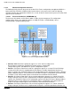
For Lockstep Channel Mode and Mirroring Mode, processor channels are paired together as a “Domain”.
• CPU1 Mirroring/Lockstep Domain 1 = Channel A + Channel B
• CPU1 Mirroring/Lockstep Domain 2 = Channel C + Channel D
• CPU2 Mirroring/Lockstep Domain 1 = Channel E + Channel F
• CPU2 Mirroring/Lockstep Domain 2 = Channel G + Channel H
• CPU3 Mirroring/Lockstep Domain 1 = Channel J + Channel K
• CPU3 Mirroring/Lockstep Domain 2 = Channel L + Channel M
• CPU4 Mirroring/Lockstep Domain 1 = Channel N + Channel P
• CPU4 Mirroring/Lockstep Domain 2 = Channel R + Channel T
•