
Technical Product Specification


Intel® Server Boards S4600LH2/T2 TPS
Revision 2.0
28
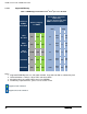
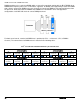
• DIMMs with different timing parameters can be installed on different slots within the same channel, but
only timings that support the slowest DIMM will be applied to all. As a consequence, faster DIMMs will be
operated at timings supported by the slowest DIMM populated.
• When one DIMM is used, it must be populated in the BLUE DIMM slot (farthest away from the CPU) of a
given channel.
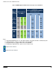
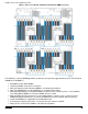
• When single, dual and quad rank DIMMs are populated for 2DPC or 3DPC, always populate the higher
number rank DIMM first (starting from the farthest slot), for example, first quad rank, then dual rank, and
last single rank DIMM.
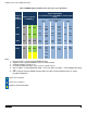
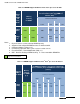
• Mixing of quad ranks DIMMs (RDIMM Raw Cards F and H for example) in one channel and three
DIMMs in other channel (3DPC) on the same CPU socket is not validated.
3.2.2.3 Publishing System Memory
The BIOS displays the “Total Memory” of the system during POST if Display Logo is disabled in the
BIOS setup. This is the total size of memory discovered by the BIOS during POST, and is the sum of
the individual sizes of installed DDR3 DIMMs in the system.
The BIOS displays the “Effective Memory” of the system in the BIOS setup. The term Effective Memory
refers to the total size of all DDR3 DIMMs that are active (not disabled) and not used as redundant
units.
The BIOS provides the total memory of the system in the main page of the BIOS setup. This total is the
same as the amount described by the first bullet above.
If Display Logo is disabled, the BIOS displays the total system memory on the diagnostic screen at the
end of POST. This total is the same as the amount described by the first bullet above.
Note: Some server operating systems do not display the total physical memory installed. What is
displayed is the amount of physical memory minus the approximate memory space used by system BIOS
components. These BIOS components include, but are not limited to:
ACPI (may vary depending on the number of PCI devices detected in the system)
ACPI NVS table
Processor microcode
Memory Mapped I/O (MMIO)
Manageability Engine (ME)
BIOS flash
3.2.2.4 Integrated Memory Controller Operating Modes
3.2.2.4.1 Independent Channel Mode
In non-ECC and x4 SDDC configurations, each channel is running independently (nonlock-step), that is, each
cache-line from memory is provided by a channel. To deliver the 64-byte cache-line of data, each channel is
bursting eight 8-byte chunks. Back to back data transfer in the same direction and within the same rank can be
sent back-to-back without any dead-cycle. The independent channel mode is the recommended method to
deliver most efficient power and bandwidth as long as the x8 SDDC is not required.
3.2.2.4.2 Lockstep Channel Mode
In lockstep channel mode the cache-line is split across channels. This is done to support Single Device Data
Correction (SDDC) for DRAM devices with 8-bit wide data ports. Also, the same address is used on both
channels, such that an address error on any channel is detectable by bad ECC. The iMC module always
accumulates 32-bytes before forwarding data so there is no latency benefit for disabling ECC.