
Technical Product Specification


Intel® Server Boards S4600LH2/T2 TPS
Revision 2.0
25
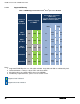
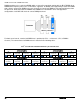
Notes:
1. Physical Rank is used to calculate DIMM Capacity.
2. Supported and validated DRAM Densities are 2Gb and 4Gb.
3. Command Address Timing is 1N.
4. For Memory Population Rules, please refer to section 3.2.2.2.
5. QR: For 3DPC – Rank Multiplication (RM) = 2; 8R: For 2DPC and 3DPC – Rank Multiplication (RM) = 4
6. QDP: Quad Die Package DRAM stacking; DDP: Dual Die Package DRAM stacking; P: Planer
monolithic DRAM Die.
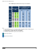
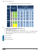
Supported and Validated
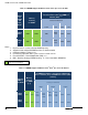
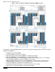
3.2.2.2 Memory Slot Identification and Population Rules
___________________________________________________________________________________
NOTE: Although mixed DIMM configurations are supported, Intel only performs platform validation on systems
that are configured with identical DIMMs installed.
___________________________________________________________________________________
Each processor provides four banks of memory, each capable of supporting up to 3 DIMMs.
DIMMs are organized into physical slots on DDR3 memory channels that belong to processor sockets.
The memory channels from processor socket 1 are identified as Channel A, B, C and D. The
memory channels from processor socket 2 are identified as Channel E, F, G, and H. The memory
channels from processor socket 3 are identified as Channel J, K, L, and M. The memory channels
from processor socket 4 are identified as N, P, R, and T.
The silk screened DIMM slot identifiers on the board provide information about the channel, and
therefore the processor to which they belong. For example, DIMM_A1 is the first slot on Channel A on
processor 1; DIMM_E1 is the first DIMM socket on Channel E on processor 2; DIMM_J1 is the first
DIMM socket on Channel J on processor 3; DIMM_N1 is the first DIMM socket on Channel N on
processor 4.
The memory slots associated with a given processor are unavailable if the corresponding processor
socket is not populated.
A processor may be installed without populating the associated memory slots provided a second
processor is installed with associated memory.
In this case, the memory is shared by the processors.
However, the platform suffers performance degradation and latency due to the remote memory.
Processor sockets are self-contained and autonomous. However, all memory subsystem support (such
as Memory RAS, Error Management,) in the BIOS setup are applied commonly across processor
sockets.
The BLUE memory slots on the server board identify the first memory slot for a given memory channel.