
Technical Product Specification

Intel® Server Boards S4600LH2/T2 TPS Product Overview
Revision 2.0
5
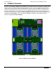
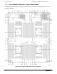
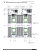
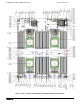
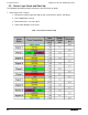
Table 2. Server Board Component / Feature Identification Table
Description
Description
A Manufacturing Mode jumper AF CPU #1 socket
B Serial ‘A’ Port (RJ45) AG CPLD programming header
C NIC 2 AH Riser Card slot #1
D NIC 1 AI CPU #4 DIMM slots – Memory Banks N and P
E RMM4 Lite connector (Option) AJ CPU #4 socket
F Video connector AK Front Panel Video connector
G CPU #2 DIMM slots – Memory Banks G and H AL Front Panel header (SSI compatible)
H CPU #1 DIMM slots – Memory Banks A and B AM CPU #1 Fan connector
I I/O Module connector (Option) AN CPU #4 Fan connector
J
eUSB Solid State Device (SSD) connector
(Option) AO CPU #4 DIMM slots – Memory Banks R and T
K Rear System Fan #2 connector AP Main Power Slot #2 (P2)
L Rear System Fan #1 connector AQ Main Power Slot #1 (P1)
M 4 Port SATA / SAS connector (Drives 4-7) AR CPU #3 DIMM slots – Memory Banks J and K
N 4 Port SATA / SAS connector (Drives 0-3) AS CPU #3 Fan connector
O
Intel® RAID C600 Upgrade Key connector
(Option) AT CPU #2 Fan connector
P Type-A USB 2.0 connector AU Fan board power connector
Q mSATA port (Option) AV PDB signal connector
R 2 Stacked USB 2.0 ports
AW 4-pin IPMB connector
S 2 Stacked USB 2.0 ports AX LCP connector
T System ID LED AY 3-pin Hot Swap Backplane SMBUS connector
U System Status LED AZ CPU #3 socket
V POST Code Diagnostic LEDs BA CPU #3 DIMM slots – Memory Banks L and M
W SATA only port #0 BB Riser Card slot #2
X Internal Serial Port BC Backup Battery
Y SATA only port #1 BD CPU #2 socket
Z Internal USB port BE CPU #2 DIMM slots – Memory Banks E and F
AA Password Clear jumper BF I/O Module connector (Option)
AB BIOS Recover jumper BG RMM4 NIC connector (Option)
AC BIOS Default jumper BH TPM connector (Option)
AD ME Force Update jumper BI Serial A Jumper
AE CPU #1 DIMM slots – Memory Banks C and D BJ BMC Debug port