
Technical Product Specification


Intel® Server Boards S4600LH2/T2 TPS
Revision 2.0
109
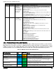
Color
State
Criticality
Description
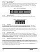
HDD HSC is off-line or degraded.
Amber
~1 Hz blink
Non-critical -
System is
operating in a
degraded state
with an impending
failure warning,
although still
functioning
Non-fatal alarm – system is likely to fail:
Critical threshold crossed – Voltage, temperature (including HSBP temp),
input power to power supply, output current for main power rail from power
supply and PROCHOT (Therm Ctrl) sensors.
VRD Hot asserted.
Minimum number of fans to cool the system not present or failed
Hard drive fault
Power Unit Redundancy sensor –
Insufficient resources offset (indicates not
enough power supplies present)
In non-sparing and non-mirroring mode if the threshold of correctable errors
is crossed within the window
Correctable memory error threshold has been reached for a failing DDR3
DIMM when the system is operating in a non-redundant mode
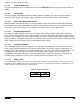
Amber
Solid on
Critical, non-
recoverable –
System is halted
Fatal alarm – system has failed or shutdown:
CPU CATERR signal asserted
MSID mismatch detected (CATERR also asserts for this case).
CPU 1 is missing
CPU Thermal Trip
No power good – power fault
DIMM failure when there is only 1 DIMM present and hence no good
memory present.
Runtime memory uncorrectable error in non-redundant mode.
DIMM Thermal Trip or equivalent
SSB Thermal Trip or equivalent
CPU ERR2 signal asserted
BMC\Video memory test failed. (Chassis ID shows blue/solid-on for this
condition)
Both uBoot BMC FW images are bad. (Chassis ID shows blue/solid-on for
this condition)
240VA fault
Fatal Error in processor initialization:
Processor family not identical
Processor model not identical
Processor core/thread counts not identical
Processor cache size not identical
Unable to synchronize processor frequency
Unable to synchronize QPI link frequency
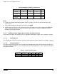
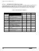
10.3
BMC Boot/Reset Status LED Indicators
During the BMC boot or BMC reset process, the System Status LED and System ID LED are used to indicate
BMC boot process transitions and states. A BMC boot will occur when AC power is first applied to the system.
A BMC reset will occur after: a BMC FW update, upon receiving a BMC cold reset command, and upon a BMC
watchdog initiated reset. The following table defines the LED states during the BMC Boot/Reset process.
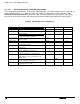
Table 56. BMC Boot/Reset Status LED Indicators
BMC Boot/Reset State
Chassis ID
LED
Status LED
Comment
BMC/Video memory test failed
Solid
Blue
Solid
Amber
Nonrecoverable condition. Contact your Intel
®
representative for
information on replacing this motherboard.
Both Universal Bootloader (u-Boot)
images bad
Solid
Blue
Solid
Amber
Nonrecoverable condition. Contact your Intel
®
representative for
information on replacing this motherboard.
BMC in u
-Boot
Blink
Blue 3Hz
Blink
Green
1Hz
Blinking green indicates degraded state (no manageability), blinking
blue indicates u-Boot is running but has not transferred control to
BMC Linux. Server will be in this state 6-8 seconds after BMC reset
while it pulls the Linux image into flash.
BMC Booting Linux
Solid
Blue
Solid
Green
Solid green with solid blue after an AC cycle/BMC reset indicates that
the control has been passed from u-Boot to BMC Linux itself. It will be
in this state for ~10-~20 seconds.
End of BMC boot/reset process.
Normal system operation
Off
Solid
Green
Indicates BMC Linux has booted and manageability functionality is up
and running. Fault/Status LEDs operate as per usual.