
Technical Product Specification


Intel® Server Boards S4600LH2/T2 TPS
Revision 2.0
102
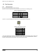
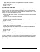
8.6.3 Chassis Intrustion Switch Header
The server board includes a 2-pin chassis intrusion header which can be used when the chassis is configured
with a chassis intrusion switch. On the server board, this header is located on the rear right side of the server
board below the internal USB header. The header has the following pin-out.
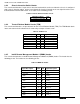
Table 51. Chassis Intrusion Header Pin-out
Signal Description
Pin#
FP_CHASSIS_INTRUSION
1
GROUND
2
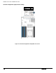
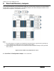
8.6.4 Trusted Platform Module Header (TPM)
The server board includes a 14-pin connector for the Trusted Platform Module (TPM). The TPM Module docks
into a connector on the baseboard and is retained by a tamper resistant screw.
Table 52. TPM Pin-out
Signal Description
Pin#
Pin#
Signal Description
Key Pin
1
2
LPC_LAD<1>
LPC_LAD<0>
3
4
GND
IRQ_SERIAL
5
6
LPC_FRAME_N
P3V3
7
8
GND
RST_IBMC_NIC_N
9
10
CLK_33M_TPM
LPC_LAD<3>
11
12
GND
GND
13
14
LPC_LAD<2>
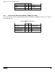
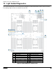
8.6.5 Intel® Remote Management Module 4 (RMM4) header
The server board includes an Intel® Remote Management Module 4 (RMM4) header. The header has the
following pin-out. The header has the following pin-out.
Table 53. RMM4 Pin header
Signal Description
Pin#
Pin#
Signal Description
3V3_AUX
1
2
MDIO
3V3_AUX
3
4
MDC
GND
5
6
TXD_0
GND
7
8
TXD_1
GND
9
10
TXD_2
GND
11
12
TXD_3
GND
13
14
TX_CTL
GND
15
16
RX_CTL
GND
17
18
RXD_0
GND
19
20
RXD_1
GND
21
22
RXD_2