
Technical Product Specification


Intel® Server Boards S4600LH2/T2 TPS
Revision 2.0
99
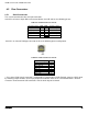
8.5 Rear Connectors
8.5.1 Serial Connectors
The server board includes two serial port connectors.
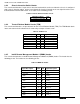
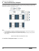
Serial-B is an internal 10-pin DH-10 connector labeled “Serial B” and has the following pin-out.
Table 46. Serial-B Connector Pin-out
Signal Description
Pin#
Pin#
Signal Description
SPA_DCD
1
2
SPA_DTR
SPA_SIN_N
3
4
GND
SPA_SOUT_N
5
6
SPA_SIN_N
SPA_DTR
7
8
SPA_CTS
GND
9
KEY
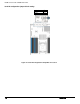
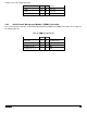
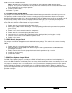
Serial-A is an external RJ45 type connector and has the following pin-out configuration.
Table 47. Serial A Connector Pin-out
Signal Description
Pin#
SPA_RTS
1
SPA_DTR
2
SPA_OUT_N
3
GND
4
SPA_RI
5
SPA_SIN_N
6
SPA_DSR
7**
SPA_CTS
8
** Pin 7 of the RJ45 Serial A connector is configurable to support either a DSR (Default) signal or a DCD signal
by switching jumper locations on the 3-pin jumper block labeled “XXX” on the server board which is located
next to the stacked external USB connectors near the back edge of the board.