
Technical Product Specification


Intel® Server Boards S4600LH2/T2 TPS
Revision 2.0
95
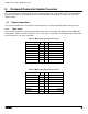
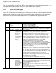
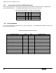
Signal Description
Pin#
Pin#
Signal Description
V_BMC_GFX_FRONT_HSYN
9
KEY
V_BMC_FRONT_DDC_SDA_CONN
11
12
V_FRONT_PRES_N
V_BMC_FRONT_DDC_SCL_CONN
13
14
P5V_VID_CONN_FNT
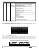
8.2.4 Intel
®
Local Control Panel Connector
The server board includes a 7-pin connector that is used when the system is configured with the Intel
®
Local
Control Panel with LCD support. On the server board this connector is labeled “LCP” and is located on the
front edge of the board. The following table provides the pin-out for this connector.
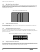
Table 39. Intel Local Control Panel Connector Pin-out ("LCP")
Signal Description
Pin#
SMB_SENSOR_3V3STBY_DATA_R0
1
GROUND
2
SMB_SENSOR_3V3STBY_CLK
3
P3V3_AUX
4
FM_LCP_ENTER_N_R
5
FM_LCP_LEFT_N_R
6
FM_LCP_RIGHT_N_R
7
8.3 On-Board Storage Connectors
The server board provides connectors for support of several storage device options. This section provides a
functional overview and pin-out of each connector.
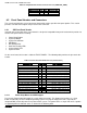
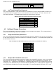
8.3.1 Single Port SATA Only Connectors
The server board includes two white single port SATA only connectors capable of transfer rates of up to 6Gb/s.
On the server board these connectors are labeled as “SATA 0” and “SATA 1”. The following table provides the
pin-out for both connectors.
Table 40. Single Port AHCI SATA Controller Connector Pin-out ("SATA 0" & "SATA 1")
Signal Description
Pin#
GROUND
1
SATA_TXP
2
SATA_TXN
3
GROUND
4
SATA_RXN
5
SATA_RXP
6
GROUND
7
8.3.2 Multiport Mini-SAS/SATA Connectors
The server board includes two 40-pin high density multiport mini-SAS/SATA connectors. On the server board,
these connectors are labeled as “SATA/SAS_0-3” supporting the chipset embedded SCU 0 controller, and
“SATA/SAS _4-7”, supporting the embedded SCU 1 controller. Both connectors can support up to four SATA
or SAS ports each. By default, only the connector labeled “SATA/SAS_0-3” is enabled and has support for up
to four SATA ports capable of transfer rates of up to 6Gb/s. The connector labeled “SATA/SAS _4-7” is only