
Technical Product Specification


Intel® Server Boards S4600LH2/T2 TPS
Revision 2.0
90
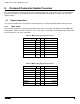
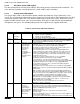
8.1.2 Main Board Power Control Signals
Power control signals are routed via connector P5. The connector provides signal and 12Vstby interface from
the PDB to the motherboard. The 3.3Vstby and 3.3V pins are provided to allow 3.3V power to the fan
monitoring circuit the PDB. The SMBus interface from the fan monitoring circuit is routed from the PDB to the
motherboard thru this connector
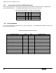
Table 30. Power Control Signals Pin-out ("P5")
Signal Description
Pin #
Pin#
Signal Description
P3V3_STBY
1
9
Return_Sense
P3V3
2
10
P12V_Remote_Sense
PMBUS_SCL
3
11
P12V_STBY
PMBUS_SDA
4
12
P12V_STBY
PSON#
5
13
P12V_STBY
PWOK
6
14
P12V_STBY
SMBAlert#
7
15
FAN_SCL
Reserved
8
16
FAN_SDA
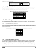
8.1.3 IO Riser Card Power Connectors
The server board supports two 3-slot riser cards a custom interconnect (3 connector blocks at 120 pins per
connector (360pins total).
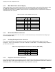
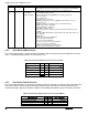
8.1.4 Hot Swap Backplane Power Connector
The server board includes one 8-pin power connector that can be cabled to provide power for hot swap
backplanes. On the server board, this connector is labeled as “HSBP PWR”. The following table provides the
pin-out for this connector.
Table 31. Hot Swap Backplane Power Connector Pin-out (“HSBP PWR")
Signal Description
Pin#
Pin#
Signal Description
P12V_240VA1
5
1
GROUND
P12V_240VA1
6
2
GROUND
P12V_240VA2
7
3
GROUND
P12V_240VA2
8
4
GROUND
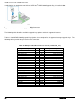
8.1.5 Peripheral Drive Power Connector
The server board includes one 6-pin power connector intended to provide power for peripheral devices such as
Optical Disk Drives (ODD) and/or Solid State Devices (SSD). On the server board this connector is labeled as
“ODD/SSD_ PWR”. The following table provides the pin-out for this connector.