
Technical Product Specification


Intel® Server Boards S4600LH2/T2 TPS
Revision 2.0
89
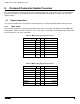
8. On-board Connector/Header Overview
This section identifies the location and pin-out for on-board connectors and headers of the server board that
provide an interface to system options/features, on-board platform management, or other user accessible
options/features.
8.1 Power Connectors
The server board includes several power connectors that are used to provide DC power to various devices.
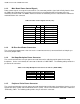
8.1.1 Main Power
Main server board power is supplied via two power connectors, connecting main power from the PDB to the
motherboard. Each connector is labeled as “P1” or “P2” on the server board. The following tables provide the
pin-out for both “P1” and “P2” connectors.
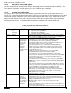
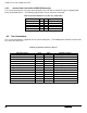
Table 28. Main Power (P1) Connector Pin-out
Signal Description
Pin #
Pin#
Signal Description
GROUND
1
9
P12V1/2
GROUND
2
10
P12V1/2
GROUND
3
11
P12V1/2
GROUND
4
12
P12V1/2
GROUND
5
13
P12V1/2
GROUND
5
14
P12V1/2
GROUND
7
15
P12V1/2
GROUND
8
16
P12V1/2
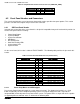
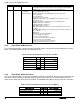
Table 29. Main Power (P2) Connector Pin-out
Signal Description
Pin #
Pin#
Signal Description
GROUND
1
9
P12V1/2
GROUND
2
10
P12V1/2
GROUND
3
11
P12V1/2
GROUND
4
12
P12V1/2
GROUND
5
13
P12V1/2
GROUND
5
14
P12V1/2
GROUND
7
15
P12V1/2
GROUND
8
16
P12V1/2