
Technical Product Specification
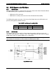
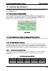

Table Of Contents
- 1. Introduction
- 2. Product Family Overview
- 3. Power Subsystem
- 3.1 Mechanical Overview
- 3.2 Power Connectors
- 3.3 Power Supply Module Efficiency
- 3.4 AC and DC Power Cord Specification Requirements
- 3.5 AC Input Specifications
- 3.5.1 Power Factor
- 3.5.2 AC Input Voltage Specification
- 3.5.3 AC Line Isolation Requirements
- 3.5.4 AC Line Dropout/Holdup
- 3.5.5 AC Line Fuse
- 3.5.6 AC Inrush
- 3.5.7 AC Line Transient Specification
- 3.5.8 Susceptibility Requirements
- 3.5.9 Electrostatic Discharge Susceptibility
- 3.5.10 Fast Transient/Burst
- 3.5.11 Radiated Immunity
- 3.5.12 Surge Immunity
- 3.5.13 Power Recovery
- 3.5.14 Voltage Interruptions
- 3.5.15 Protection Circuits
- 3.5.16 Over-current Protection (OCP)
- 3.5.17 Over-voltage Protection (OVP)
- 3.5.18 Over-temperature Protection (OTP)
- 3.6 1600W DC Power Supply Support
- 3.6.1 Power Supply Module Efficiency
- 3.6.2 DC Inlet Connector
- 3.6.3 DC Input Voltage Specification
- 3.6.4 DC Holdup/Dropout Time
- 3.6.5 DC Line Fuse
- 3.6.6 DC Inrush
- 3.6.7 DC Line Surge Voltages (Line Transients)
- 3.6.8 Residual Voltage Immunity in Standby Mode
- 3.6.9 Protection Circuits
- 3.6.10 Over Temperature Protection (OTP)
- 3.7 Cold Redundancy Support
- 3.8 Closed Loop System Throttling (CLST)
- 3.9 Smart Ride Through (SmaRT)
- 3.10 Power Supply Status LED
- 4. Thermal Management
- 5. System Storage and Peripheral Drive Bays Overview
- 6. Storage Controller Options Overview
- 7. Front Control Panel and I/O Panel Overview
- 8. Intel® Local Control Panel
- 9. PCI Riser Card Support
- 10. Additonal System Boards
- 11. Front Panel
- 12. IO Module Support
- 13. Intel® Intelligent Power Node Manager (NM)
- Appendix A: Integration and Usage Tip
- Appendix B: POST Code Diagnostic LED Decoder
- Appendix C: POST Code Errors
- Glossary
- Reference Documents
Intel® Server System R2000LH2/T2 Product Family TPS PCI Riser Card Support
Revision 1.0
81
9.4
Riser Slot Mapping
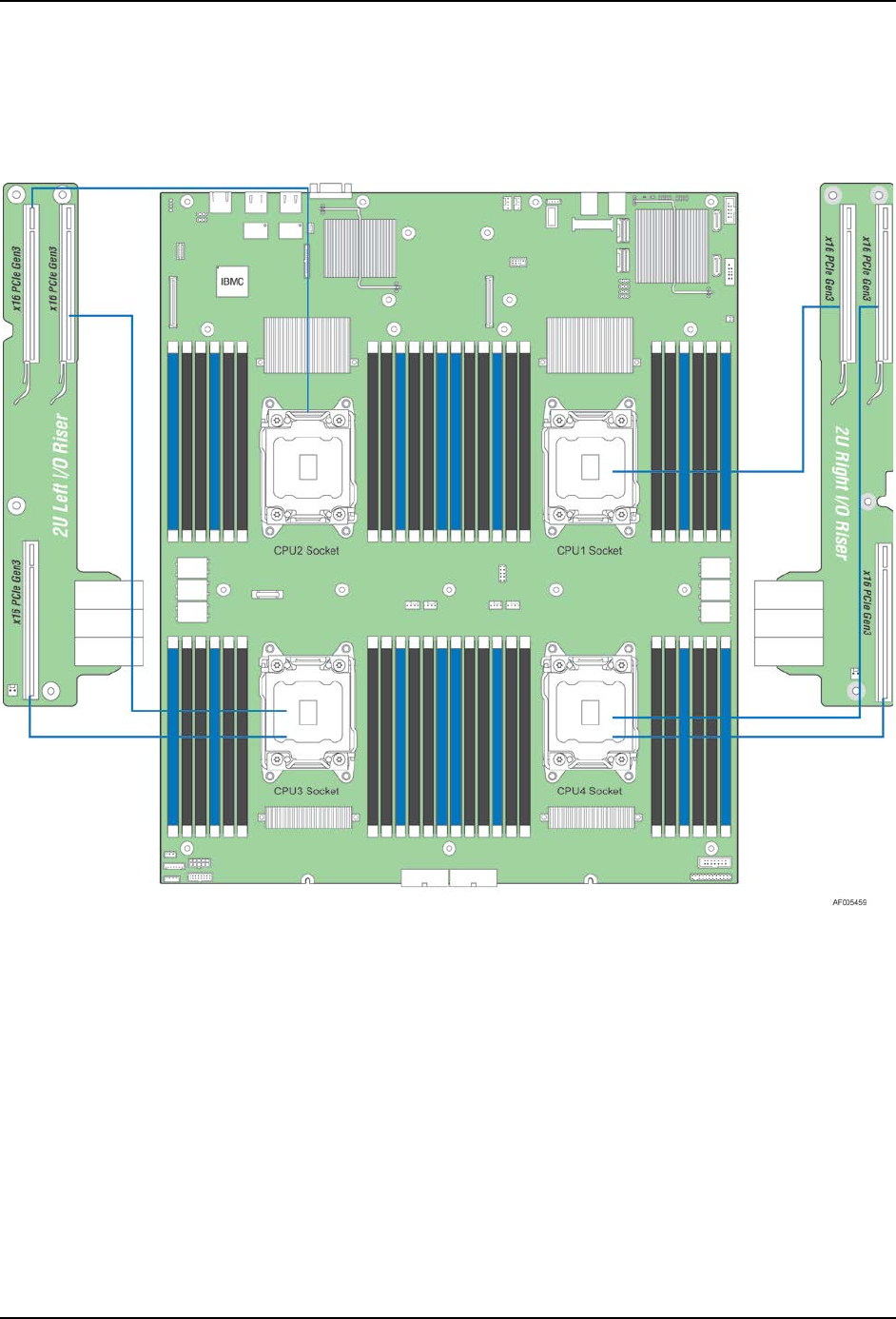
A total of 48 PCIe Gen3 signals are routed to each of the IO Risers. For IO Riser 1 (Right) there
are 16 lanes from CPU 1 and 32 lanes from CPU 4. For IO Riser 2 (Left), there are 16 lanes
from CPU 2 and 32 lanes from CPU 3.
Figure 69. IO Riser CPU Mapping