
Technical Product Specification
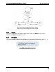

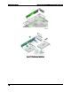
Table Of Contents
- 1. Introduction
- 2. Product Family Overview
- 3. Power Subsystem
- 3.1 Mechanical Overview
- 3.2 Power Connectors
- 3.3 Power Supply Module Efficiency
- 3.4 AC and DC Power Cord Specification Requirements
- 3.5 AC Input Specifications
- 3.5.1 Power Factor
- 3.5.2 AC Input Voltage Specification
- 3.5.3 AC Line Isolation Requirements
- 3.5.4 AC Line Dropout/Holdup
- 3.5.5 AC Line Fuse
- 3.5.6 AC Inrush
- 3.5.7 AC Line Transient Specification
- 3.5.8 Susceptibility Requirements
- 3.5.9 Electrostatic Discharge Susceptibility
- 3.5.10 Fast Transient/Burst
- 3.5.11 Radiated Immunity
- 3.5.12 Surge Immunity
- 3.5.13 Power Recovery
- 3.5.14 Voltage Interruptions
- 3.5.15 Protection Circuits
- 3.5.16 Over-current Protection (OCP)
- 3.5.17 Over-voltage Protection (OVP)
- 3.5.18 Over-temperature Protection (OTP)
- 3.6 1600W DC Power Supply Support
- 3.6.1 Power Supply Module Efficiency
- 3.6.2 DC Inlet Connector
- 3.6.3 DC Input Voltage Specification
- 3.6.4 DC Holdup/Dropout Time
- 3.6.5 DC Line Fuse
- 3.6.6 DC Inrush
- 3.6.7 DC Line Surge Voltages (Line Transients)
- 3.6.8 Residual Voltage Immunity in Standby Mode
- 3.6.9 Protection Circuits
- 3.6.10 Over Temperature Protection (OTP)
- 3.7 Cold Redundancy Support
- 3.8 Closed Loop System Throttling (CLST)
- 3.9 Smart Ride Through (SmaRT)
- 3.10 Power Supply Status LED
- 4. Thermal Management
- 5. System Storage and Peripheral Drive Bays Overview
- 6. Storage Controller Options Overview
- 7. Front Control Panel and I/O Panel Overview
- 8. Intel® Local Control Panel
- 9. PCI Riser Card Support
- 10. Additonal System Boards
- 11. Front Panel
- 12. IO Module Support
- 13. Intel® Intelligent Power Node Manager (NM)
- Appendix A: Integration and Usage Tip
- Appendix B: POST Code Diagnostic LED Decoder
- Appendix C: POST Code Errors
- Glossary
- Reference Documents

Intel® Server System R2000LH2/T2 Product Family TPS PCI Riser Card Support
Revision 1.0
77
9. PCI Riser Card Support
The system includes two riser card slots on the server board. Available riser cards can be used
in either slot. This chapter provides an overview of each available riser card and describes the
server board features and architecture supporting them.
9.1
Riser Slot Overview
The server system supports two 3-slot riser cards identified by IO Riser 1 (Right) and IO Riser 2
(Left). The two 3- slot PCIe Risers each support up to x48 lanes of PCIe Gen3 through a custom
interconnect (3 connector blocks at 120 pins per connector, 360pins total).The PCIe signals for
each riser card slot are supported each by two installed processors.
Additional support:
One double wide GPGPU or Graphics card per riser (up to 300W active supported,
passive not supported)
OR
Two single wide GPGPU or Graphics cards per riser (up to 150W active supported;
passive not supported)
OR
Two single wide full height, full length (FHFL) cards per riser (25W supported for each)
OR
Three single wide full height, half length (FHHL) cards per riser (one of these are internal
only slots). Un-shadowed PCIe slots support 25W each and shadowed supports 10W
each
3.3V VR for PCIe card power is located on the riser