
Technical Product Specification
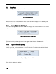
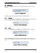
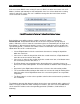

Table Of Contents
- 1. Introduction
- 2. Product Family Overview
- 3. Power Subsystem
- 3.1 Mechanical Overview
- 3.2 Power Connectors
- 3.3 Power Supply Module Efficiency
- 3.4 AC and DC Power Cord Specification Requirements
- 3.5 AC Input Specifications
- 3.5.1 Power Factor
- 3.5.2 AC Input Voltage Specification
- 3.5.3 AC Line Isolation Requirements
- 3.5.4 AC Line Dropout/Holdup
- 3.5.5 AC Line Fuse
- 3.5.6 AC Inrush
- 3.5.7 AC Line Transient Specification
- 3.5.8 Susceptibility Requirements
- 3.5.9 Electrostatic Discharge Susceptibility
- 3.5.10 Fast Transient/Burst
- 3.5.11 Radiated Immunity
- 3.5.12 Surge Immunity
- 3.5.13 Power Recovery
- 3.5.14 Voltage Interruptions
- 3.5.15 Protection Circuits
- 3.5.16 Over-current Protection (OCP)
- 3.5.17 Over-voltage Protection (OVP)
- 3.5.18 Over-temperature Protection (OTP)
- 3.6 1600W DC Power Supply Support
- 3.6.1 Power Supply Module Efficiency
- 3.6.2 DC Inlet Connector
- 3.6.3 DC Input Voltage Specification
- 3.6.4 DC Holdup/Dropout Time
- 3.6.5 DC Line Fuse
- 3.6.6 DC Inrush
- 3.6.7 DC Line Surge Voltages (Line Transients)
- 3.6.8 Residual Voltage Immunity in Standby Mode
- 3.6.9 Protection Circuits
- 3.6.10 Over Temperature Protection (OTP)
- 3.7 Cold Redundancy Support
- 3.8 Closed Loop System Throttling (CLST)
- 3.9 Smart Ride Through (SmaRT)
- 3.10 Power Supply Status LED
- 4. Thermal Management
- 5. System Storage and Peripheral Drive Bays Overview
- 6. Storage Controller Options Overview
- 7. Front Control Panel and I/O Panel Overview
- 8. Intel® Local Control Panel
- 9. PCI Riser Card Support
- 10. Additonal System Boards
- 11. Front Panel
- 12. IO Module Support
- 13. Intel® Intelligent Power Node Manager (NM)
- Appendix A: Integration and Usage Tip
- Appendix B: POST Code Diagnostic LED Decoder
- Appendix C: POST Code Errors
- Glossary
- Reference Documents

Intel® Local Control Panel Intel® Server System R2000LH2/T2 Product Family TPS
Revision 1.0
76
8.5.5
Banner
When the user selects Banner in the Config menu, the following options will be displayed. The
selected item will be set as banner and the same will be displayed from next banner screen
onwards.
Figure 66. Banner Configuration Menu
Each menu item is explained as follows:
Server Name: Displays the value specified in the product name in the product FRU
information in the main board BMC FRU. The Server Name is the default banner.
Server Model: Displays the value specified in the product part number in the product
FRU information in the main board BMC FRU.
Error: Displays the last active system event. The last active event may be degraded,
non-critical, or critical only. It will not display an informational message. If the system is
healthy then displays System Health Ok.
BMC IP: Displays the IPv4 or IPv6 address of BMC IP. If the BMC IP address is not
configured, nothing is displayed.
RMM4 IP: Displays the IPv4 or IPv6 address of RMM4 dedicated LAN IP. If the RMM4
IP is not set or not present, nothing is displayed.
Power: Displays the current system power consumption in watts. The power consumed
will be refreshed every minute.
Last PC: Displays last BIOS post code.
Custom string: Displays a customizable text string. The custom text string is modifiable
through BIOS setup.
Custom Logo: Displays a customizable bitmap logo. The OEM customized logo is
programmed by the OEM and maintained during subsequent firmware updates.
For additional information, see the Intel
®
Local Control Panel for EPSD Platforms Based on the
Intel
®
Xeon
®
Processor E5 -4600/2600/2400/1600/1400 Product Families Technical Product
Specification.