
Technical Product Specification
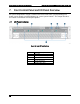

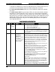

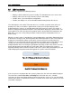
Table Of Contents
- 1. Introduction
- 2. Product Family Overview
- 3. Power Subsystem
- 3.1 Mechanical Overview
- 3.2 Power Connectors
- 3.3 Power Supply Module Efficiency
- 3.4 AC and DC Power Cord Specification Requirements
- 3.5 AC Input Specifications
- 3.5.1 Power Factor
- 3.5.2 AC Input Voltage Specification
- 3.5.3 AC Line Isolation Requirements
- 3.5.4 AC Line Dropout/Holdup
- 3.5.5 AC Line Fuse
- 3.5.6 AC Inrush
- 3.5.7 AC Line Transient Specification
- 3.5.8 Susceptibility Requirements
- 3.5.9 Electrostatic Discharge Susceptibility
- 3.5.10 Fast Transient/Burst
- 3.5.11 Radiated Immunity
- 3.5.12 Surge Immunity
- 3.5.13 Power Recovery
- 3.5.14 Voltage Interruptions
- 3.5.15 Protection Circuits
- 3.5.16 Over-current Protection (OCP)
- 3.5.17 Over-voltage Protection (OVP)
- 3.5.18 Over-temperature Protection (OTP)
- 3.6 1600W DC Power Supply Support
- 3.6.1 Power Supply Module Efficiency
- 3.6.2 DC Inlet Connector
- 3.6.3 DC Input Voltage Specification
- 3.6.4 DC Holdup/Dropout Time
- 3.6.5 DC Line Fuse
- 3.6.6 DC Inrush
- 3.6.7 DC Line Surge Voltages (Line Transients)
- 3.6.8 Residual Voltage Immunity in Standby Mode
- 3.6.9 Protection Circuits
- 3.6.10 Over Temperature Protection (OTP)
- 3.7 Cold Redundancy Support
- 3.8 Closed Loop System Throttling (CLST)
- 3.9 Smart Ride Through (SmaRT)
- 3.10 Power Supply Status LED
- 4. Thermal Management
- 5. System Storage and Peripheral Drive Bays Overview
- 6. Storage Controller Options Overview
- 7. Front Control Panel and I/O Panel Overview
- 8. Intel® Local Control Panel
- 9. PCI Riser Card Support
- 10. Additonal System Boards
- 11. Front Panel
- 12. IO Module Support
- 13. Intel® Intelligent Power Node Manager (NM)
- Appendix A: Integration and Usage Tip
- Appendix B: POST Code Diagnostic LED Decoder
- Appendix C: POST Code Errors
- Glossary
- Reference Documents
Intel® Server System R2000LH2/T2 Product Family TPS Front Control Panel and I/O Panel Overview
Revision 1.0
61
7.2
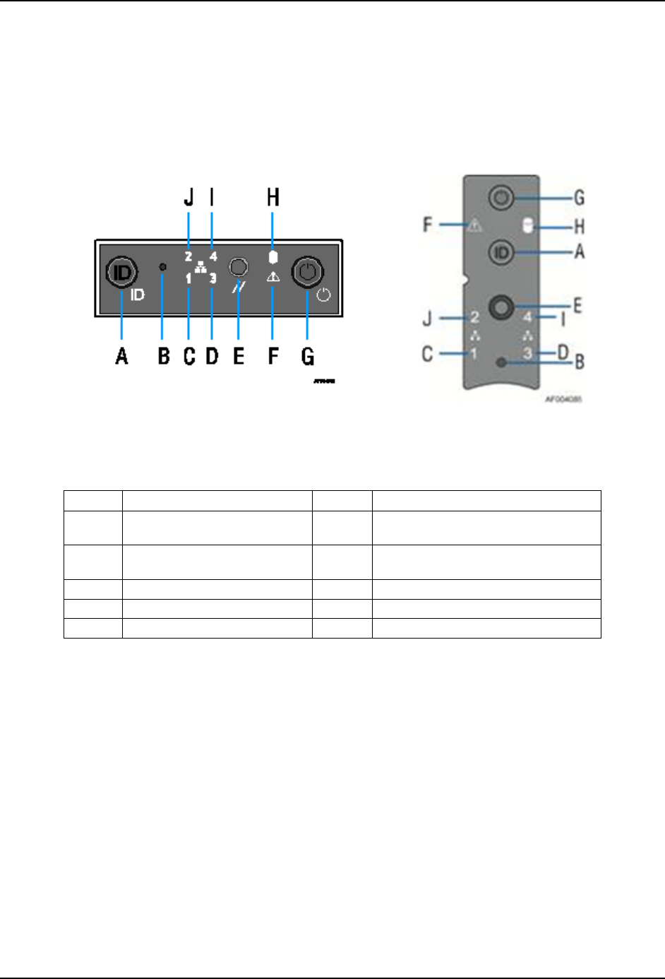
Control Panel Features
The system includes a control panel that provides push button system controls and LED
indicators for several system features. Depending on the hard drive configuration, the front
control panel may come in either of two formats; however, both provide the same functionality.
This section provides a description for each front control panel feature.
Figure 46. Front Control Panel Features
Label
Description
Label
Description
A
System ID Button w/Integrated
LED
F
System Status LED
B
NMI Button (recessed, tool
required for use)
G
Power / Sleep Button w/Integrated
LED
C
NIC-1 Activity LED
H
Hard Drive Activity LED
D
Not Used
I
Not Used
E
System Cold Reset Button
J
NIC-2 Activity LED
A – System ID Button w/Integrated LED: Toggles the integrated ID LED and the Blue
server board ID LED on and off. The System ID LED is used to identify the system for
maintenance when installed in a rack of similar server systems. The System ID LED can
also be toggled on and off remotely using the IPMI Chassis Identify command which will
cause the LED to blink for 15 seconds.
B – NMI Button: When the NMI button is pressed, it puts the server in a halt state and
issues a non-maskable interrupt (NMI). This can be useful when performing diagnostics
for a given issue where a memory download is necessary to help determine the cause of
the problem. To prevent an inadvertent system halt, the actual NMI button is located
behind the Front Control Panel faceplate where it is only accessible with the use of a
small tipped tool like a pin or paper clip.
C, D, I and J – Network Activity LEDs: The Front Control Panel includes an activity
LED indicator for each on-board Network Interface Controller (NIC). When a network link