
Technical Product Specification
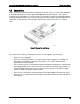
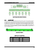
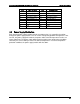
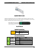
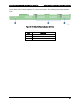

Table Of Contents
- 1. Introduction
- 2. Product Family Overview
- 3. Power Subsystem
- 3.1 Mechanical Overview
- 3.2 Power Connectors
- 3.3 Power Supply Module Efficiency
- 3.4 AC and DC Power Cord Specification Requirements
- 3.5 AC Input Specifications
- 3.5.1 Power Factor
- 3.5.2 AC Input Voltage Specification
- 3.5.3 AC Line Isolation Requirements
- 3.5.4 AC Line Dropout/Holdup
- 3.5.5 AC Line Fuse
- 3.5.6 AC Inrush
- 3.5.7 AC Line Transient Specification
- 3.5.8 Susceptibility Requirements
- 3.5.9 Electrostatic Discharge Susceptibility
- 3.5.10 Fast Transient/Burst
- 3.5.11 Radiated Immunity
- 3.5.12 Surge Immunity
- 3.5.13 Power Recovery
- 3.5.14 Voltage Interruptions
- 3.5.15 Protection Circuits
- 3.5.16 Over-current Protection (OCP)
- 3.5.17 Over-voltage Protection (OVP)
- 3.5.18 Over-temperature Protection (OTP)
- 3.6 1600W DC Power Supply Support
- 3.6.1 Power Supply Module Efficiency
- 3.6.2 DC Inlet Connector
- 3.6.3 DC Input Voltage Specification
- 3.6.4 DC Holdup/Dropout Time
- 3.6.5 DC Line Fuse
- 3.6.6 DC Inrush
- 3.6.7 DC Line Surge Voltages (Line Transients)
- 3.6.8 Residual Voltage Immunity in Standby Mode
- 3.6.9 Protection Circuits
- 3.6.10 Over Temperature Protection (OTP)
- 3.7 Cold Redundancy Support
- 3.8 Closed Loop System Throttling (CLST)
- 3.9 Smart Ride Through (SmaRT)
- 3.10 Power Supply Status LED
- 4. Thermal Management
- 5. System Storage and Peripheral Drive Bays Overview
- 6. Storage Controller Options Overview
- 7. Front Control Panel and I/O Panel Overview
- 8. Intel® Local Control Panel
- 9. PCI Riser Card Support
- 10. Additonal System Boards
- 11. Front Panel
- 12. IO Module Support
- 13. Intel® Intelligent Power Node Manager (NM)
- Appendix A: Integration and Usage Tip
- Appendix B: POST Code Diagnostic LED Decoder
- Appendix C: POST Code Errors
- Glossary
- Reference Documents

Intel® Server System R2000LH2/T2 Product Family TPS Thermal Management
Revision 1.0
43
Pin #
Signal Description
Pin #
Signal Description
9
FAN_TACH_11_A
10
FAN_TACH_9_A
11
FAN_TACH_11_B
12
FAN_TACH_9_B
13
FAN_FAULT_LED_10
14
FAN_FAULT_LED_8
15
FAN_FAULT_LED_11
16
FAN_FAULT_LED_9
17
FAN_PRESENT_10
18
FAN_PRESENT_8
19
FAN_PRESENT_11
20
FAN_PRESENT_9
21
PWM_4
22
PWM_3
23
P12V
24
P12V2
25
P12V
26
P12V2
4.4
Power Supply Module Fan
Each installed power supply module includes one 40-mm fan. It is responsible for airflow
through the power supply module. This fan is NOT managed by platform management. If this
fan fails, the power supply will continue to operate until its internal temperature reaches an
upper critical limit. The power supply will be protected against over temperature conditions
caused by loss of fan cooling or excessive ambient temperature. In an over-temperature
protection condition, the power supply module will shut down.