
Technical Product Specification
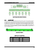
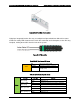

Table Of Contents
- 1. Introduction
- 2. Product Family Overview
- 3. Power Subsystem
- 3.1 Mechanical Overview
- 3.2 Power Connectors
- 3.3 Power Supply Module Efficiency
- 3.4 AC and DC Power Cord Specification Requirements
- 3.5 AC Input Specifications
- 3.5.1 Power Factor
- 3.5.2 AC Input Voltage Specification
- 3.5.3 AC Line Isolation Requirements
- 3.5.4 AC Line Dropout/Holdup
- 3.5.5 AC Line Fuse
- 3.5.6 AC Inrush
- 3.5.7 AC Line Transient Specification
- 3.5.8 Susceptibility Requirements
- 3.5.9 Electrostatic Discharge Susceptibility
- 3.5.10 Fast Transient/Burst
- 3.5.11 Radiated Immunity
- 3.5.12 Surge Immunity
- 3.5.13 Power Recovery
- 3.5.14 Voltage Interruptions
- 3.5.15 Protection Circuits
- 3.5.16 Over-current Protection (OCP)
- 3.5.17 Over-voltage Protection (OVP)
- 3.5.18 Over-temperature Protection (OTP)
- 3.6 1600W DC Power Supply Support
- 3.6.1 Power Supply Module Efficiency
- 3.6.2 DC Inlet Connector
- 3.6.3 DC Input Voltage Specification
- 3.6.4 DC Holdup/Dropout Time
- 3.6.5 DC Line Fuse
- 3.6.6 DC Inrush
- 3.6.7 DC Line Surge Voltages (Line Transients)
- 3.6.8 Residual Voltage Immunity in Standby Mode
- 3.6.9 Protection Circuits
- 3.6.10 Over Temperature Protection (OTP)
- 3.7 Cold Redundancy Support
- 3.8 Closed Loop System Throttling (CLST)
- 3.9 Smart Ride Through (SmaRT)
- 3.10 Power Supply Status LED
- 4. Thermal Management
- 5. System Storage and Peripheral Drive Bays Overview
- 6. Storage Controller Options Overview
- 7. Front Control Panel and I/O Panel Overview
- 8. Intel® Local Control Panel
- 9. PCI Riser Card Support
- 10. Additonal System Boards
- 11. Front Panel
- 12. IO Module Support
- 13. Intel® Intelligent Power Node Manager (NM)
- Appendix A: Integration and Usage Tip
- Appendix B: POST Code Diagnostic LED Decoder
- Appendix C: POST Code Errors
- Glossary
- Reference Documents
Intel® Server System R2000LH2/T2 Product Family TPS Thermal Management
Revision 1.0
39
4.3
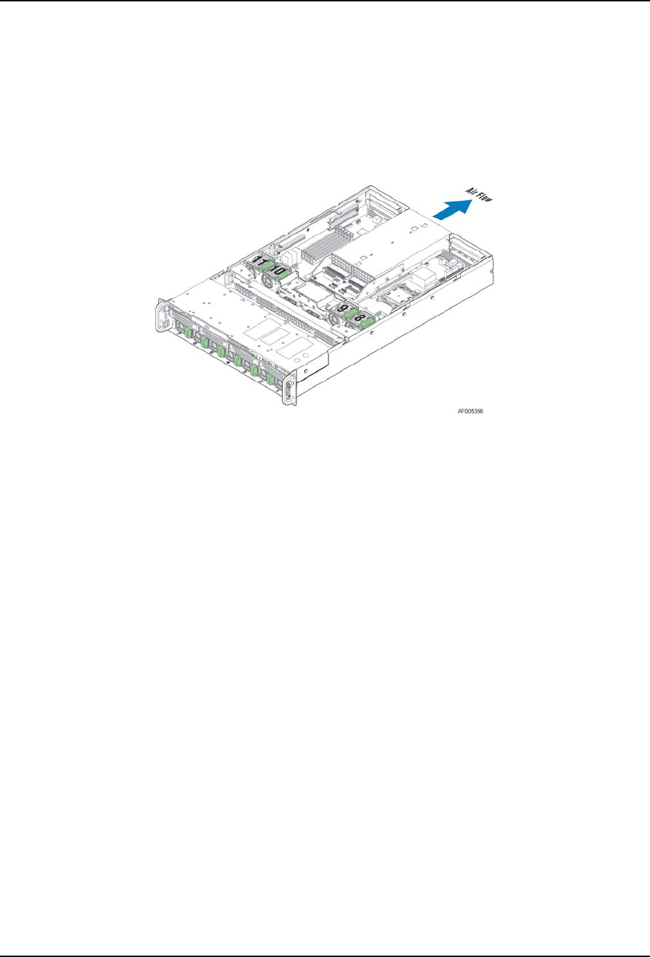
System Fans
Eleven system fans provide the primary airflow for the system. There are seven lower 40x56mm
a dual rotor hot swap fans and four upper 40x56MM dual rotor hot swap fans. The system is
designed for fan redundancy. If a single fan fails, the remaining system fans along with platform
management will provide the necessary air flow and make other platform operating adjustments
to maintain system thermals. Fan redundancy will be lost if more than one fan is in a failed
state.
Figure 21. System Fan Identification
The system fan assembly is designed for ease of use and supports several features:
Each fan is hot-swappable.
Each fan is designed for tool-less insertion and extraction from the fan assembly. For
instructions on installing or removing a fan module, see the Intel
®
Server System
R2000LH2/LT2 Service Guide.
Fan speed for each fan is controlled by integrated platform management as controlled by
the integrated BMC on the server board. As system thermals fluctuate high and low, the
integrated BMC firmware will increase and decrease the speeds to specific fans within
the fan assembly to regulate system thermals.
Each fan has a tachometer signal that allows the integrated BMC to monitor their status.
Each fan has an integrated fault LED. Platform management illuminates the fault LED for
the failing fan.