
Technical Product Specification
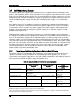

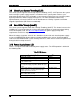

Table Of Contents
- 1. Introduction
- 2. Product Family Overview
- 3. Power Subsystem
- 3.1 Mechanical Overview
- 3.2 Power Connectors
- 3.3 Power Supply Module Efficiency
- 3.4 AC and DC Power Cord Specification Requirements
- 3.5 AC Input Specifications
- 3.5.1 Power Factor
- 3.5.2 AC Input Voltage Specification
- 3.5.3 AC Line Isolation Requirements
- 3.5.4 AC Line Dropout/Holdup
- 3.5.5 AC Line Fuse
- 3.5.6 AC Inrush
- 3.5.7 AC Line Transient Specification
- 3.5.8 Susceptibility Requirements
- 3.5.9 Electrostatic Discharge Susceptibility
- 3.5.10 Fast Transient/Burst
- 3.5.11 Radiated Immunity
- 3.5.12 Surge Immunity
- 3.5.13 Power Recovery
- 3.5.14 Voltage Interruptions
- 3.5.15 Protection Circuits
- 3.5.16 Over-current Protection (OCP)
- 3.5.17 Over-voltage Protection (OVP)
- 3.5.18 Over-temperature Protection (OTP)
- 3.6 1600W DC Power Supply Support
- 3.6.1 Power Supply Module Efficiency
- 3.6.2 DC Inlet Connector
- 3.6.3 DC Input Voltage Specification
- 3.6.4 DC Holdup/Dropout Time
- 3.6.5 DC Line Fuse
- 3.6.6 DC Inrush
- 3.6.7 DC Line Surge Voltages (Line Transients)
- 3.6.8 Residual Voltage Immunity in Standby Mode
- 3.6.9 Protection Circuits
- 3.6.10 Over Temperature Protection (OTP)
- 3.7 Cold Redundancy Support
- 3.8 Closed Loop System Throttling (CLST)
- 3.9 Smart Ride Through (SmaRT)
- 3.10 Power Supply Status LED
- 4. Thermal Management
- 5. System Storage and Peripheral Drive Bays Overview
- 6. Storage Controller Options Overview
- 7. Front Control Panel and I/O Panel Overview
- 8. Intel® Local Control Panel
- 9. PCI Riser Card Support
- 10. Additonal System Boards
- 11. Front Panel
- 12. IO Module Support
- 13. Intel® Intelligent Power Node Manager (NM)
- Appendix A: Integration and Usage Tip
- Appendix B: POST Code Diagnostic LED Decoder
- Appendix C: POST Code Errors
- Glossary
- Reference Documents

Thermal Management Intel® Server System R2000LH2/T2 Product Family TPS
Revision 1.0
36
Selecting an altitude range that is lower than the actual altitude the system will be operating at,
can cause the fan control system to operate less efficiently, leading to higher system thermals
and lower system performance. If the altitude range selected is higher than the actual altitude
the system will be operating at, the fan control system may provide better cooling but with
higher acoustics and higher fan power consumption. If the altitude is not known, selecting a
higher altitude is recommended in order to provide sufficient cooling.
4.2.3
Set Fan Profile
This option sets the desired Fan Profile. Available settings include [Performance] and [Acoustic].
The Acoustic mode offers the best acoustic experience and appropriate cooling capability
supporting the majority of the add-in cards used. Performance mode is designed to provide
sufficient cooling capability covering all kinds of add-in cards on the market.
4.2.4
Fan PWM Offset
This option is reserved for manual adjustment to the minimum fan speed curves. The valid
range is from [0 to 100] which stands for 0% to 100% PWM adding to the minimum fan speed.
This feature is valid when Quiet Fan Idle Mode is at Enabled state. The default setting is [0].
4.2.5
Quiet Fan Idle Mode
This feature can be [Enabled] or [Disabled]. If enabled, the fans will either shift to a lower speed
or stop when the aggregate sensor temperatures are satisfied, indicating the system is at ideal
thermal/light loading conditions. When the aggregate sensor temperatures are not satisfied, the
fans will shift back to normal control curves. If disabled, the fans will never shift to lower fan
speed or stop, regardless of whether the aggregate sensor temperatures are satisfied or not.
The default setting is [Disabled].
Note: The features above may or may not be in effect and depends on the actual thermal
characteristics of the specified system.