
Technical Product Specification
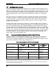

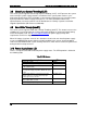


Table Of Contents
- 1. Introduction
- 2. Product Family Overview
- 3. Power Subsystem
- 3.1 Mechanical Overview
- 3.2 Power Connectors
- 3.3 Power Supply Module Efficiency
- 3.4 AC and DC Power Cord Specification Requirements
- 3.5 AC Input Specifications
- 3.5.1 Power Factor
- 3.5.2 AC Input Voltage Specification
- 3.5.3 AC Line Isolation Requirements
- 3.5.4 AC Line Dropout/Holdup
- 3.5.5 AC Line Fuse
- 3.5.6 AC Inrush
- 3.5.7 AC Line Transient Specification
- 3.5.8 Susceptibility Requirements
- 3.5.9 Electrostatic Discharge Susceptibility
- 3.5.10 Fast Transient/Burst
- 3.5.11 Radiated Immunity
- 3.5.12 Surge Immunity
- 3.5.13 Power Recovery
- 3.5.14 Voltage Interruptions
- 3.5.15 Protection Circuits
- 3.5.16 Over-current Protection (OCP)
- 3.5.17 Over-voltage Protection (OVP)
- 3.5.18 Over-temperature Protection (OTP)
- 3.6 1600W DC Power Supply Support
- 3.6.1 Power Supply Module Efficiency
- 3.6.2 DC Inlet Connector
- 3.6.3 DC Input Voltage Specification
- 3.6.4 DC Holdup/Dropout Time
- 3.6.5 DC Line Fuse
- 3.6.6 DC Inrush
- 3.6.7 DC Line Surge Voltages (Line Transients)
- 3.6.8 Residual Voltage Immunity in Standby Mode
- 3.6.9 Protection Circuits
- 3.6.10 Over Temperature Protection (OTP)
- 3.7 Cold Redundancy Support
- 3.8 Closed Loop System Throttling (CLST)
- 3.9 Smart Ride Through (SmaRT)
- 3.10 Power Supply Status LED
- 4. Thermal Management
- 5. System Storage and Peripheral Drive Bays Overview
- 6. Storage Controller Options Overview
- 7. Front Control Panel and I/O Panel Overview
- 8. Intel® Local Control Panel
- 9. PCI Riser Card Support
- 10. Additonal System Boards
- 11. Front Panel
- 12. IO Module Support
- 13. Intel® Intelligent Power Node Manager (NM)
- Appendix A: Integration and Usage Tip
- Appendix B: POST Code Diagnostic LED Decoder
- Appendix C: POST Code Errors
- Glossary
- Reference Documents

Thermal Management Intel® Server System R2000LH2/T2 Product Family TPS
Revision 1.0
34
- DIMM Population Rules on CPU-1 – Install DIMMs in order; Channels A, B, C, and
D. Start with the first DIMM (Blue Slot) on each channel, then slot 2, and then slot 3.
Only remove factory installed DIMM blanks when populating the slot with memory.
- DIMM Population on CPU-2 – Install DIMMs in order; Channels E, F, G, and H.
Start with the first DIMM (Blue Slot) on each channel, then slot 2, and then slot 3.
Only remove factory installed DIMM blanks when populating the slot with memory.
- The following system configurations require that specific memory slots be populated
at all times using either a DIMM or supplied DIMM Blank.
- DIMM Population Rules on CPU-3– Install DIMMs in order; Channels J, K, L, and
M. Start with the first DIMM (Blue Slot) on each channel, then slot 2, and then slot 3.
Only remove factory installed DIMM blanks when populating the slot with memory.
- DIMM Population on CPU-4 – Install DIMMs in order; Channels N, P, R, and T.
Start with the first DIMM (Blue Slot) on each channel, then slot 2, and then slot 3.
Only remove factory installed DIMM blanks when populating the slot with memory.
All hard drive bays must be populated. The hard drive carriers can be populated with a
hard drive or supplied drive blank.
With the system operating, the air duct must be installed at all times.
In single power supply configurations, the second power supply bay must have the
supplied filler blank installed at all times.
The system must be configured with dual power supplies for the system to support fan
redundancy.
The system top-cover must be installed at all times when the system is in operation. The
only exception to this requirement is to hot replace a failed system fan, in which case the
top cover can be removed for no more than 3 minutes at a time.