
Technical Product Specification
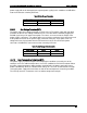
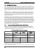


Table Of Contents
- 1. Introduction
- 2. Product Family Overview
- 3. Power Subsystem
- 3.1 Mechanical Overview
- 3.2 Power Connectors
- 3.3 Power Supply Module Efficiency
- 3.4 AC and DC Power Cord Specification Requirements
- 3.5 AC Input Specifications
- 3.5.1 Power Factor
- 3.5.2 AC Input Voltage Specification
- 3.5.3 AC Line Isolation Requirements
- 3.5.4 AC Line Dropout/Holdup
- 3.5.5 AC Line Fuse
- 3.5.6 AC Inrush
- 3.5.7 AC Line Transient Specification
- 3.5.8 Susceptibility Requirements
- 3.5.9 Electrostatic Discharge Susceptibility
- 3.5.10 Fast Transient/Burst
- 3.5.11 Radiated Immunity
- 3.5.12 Surge Immunity
- 3.5.13 Power Recovery
- 3.5.14 Voltage Interruptions
- 3.5.15 Protection Circuits
- 3.5.16 Over-current Protection (OCP)
- 3.5.17 Over-voltage Protection (OVP)
- 3.5.18 Over-temperature Protection (OTP)
- 3.6 1600W DC Power Supply Support
- 3.6.1 Power Supply Module Efficiency
- 3.6.2 DC Inlet Connector
- 3.6.3 DC Input Voltage Specification
- 3.6.4 DC Holdup/Dropout Time
- 3.6.5 DC Line Fuse
- 3.6.6 DC Inrush
- 3.6.7 DC Line Surge Voltages (Line Transients)
- 3.6.8 Residual Voltage Immunity in Standby Mode
- 3.6.9 Protection Circuits
- 3.6.10 Over Temperature Protection (OTP)
- 3.7 Cold Redundancy Support
- 3.8 Closed Loop System Throttling (CLST)
- 3.9 Smart Ride Through (SmaRT)
- 3.10 Power Supply Status LED
- 4. Thermal Management
- 5. System Storage and Peripheral Drive Bays Overview
- 6. Storage Controller Options Overview
- 7. Front Control Panel and I/O Panel Overview
- 8. Intel® Local Control Panel
- 9. PCI Riser Card Support
- 10. Additonal System Boards
- 11. Front Panel
- 12. IO Module Support
- 13. Intel® Intelligent Power Node Manager (NM)
- Appendix A: Integration and Usage Tip
- Appendix B: POST Code Diagnostic LED Decoder
- Appendix C: POST Code Errors
- Glossary
- Reference Documents

Intel® Server System R2000LH2/T2 Product Family TPS Power Subsystem
Revision 1.0
29
power supply will not be damaged from repeated power cycling in this condition. 12VSB will be
auto-recovered after removing OCP limit.
Table 20. Over Current Protection
Output Voltage
Input Voltage Range
Over Current Limits
+12V
38 – 75VDC
168A min
12VSB
38 – 75VDC
3.6A min
3.6.9.2
Over Voltage Protection (OVP)
The power supply over voltage protection is locally sensed. The power supply will shut down
and latch off after an over voltage condition occurs. This latch will be cleared by toggling the
PSON# signal or by a DC power interruption. The values are measured at the output of the
power supply’s connectors. The voltage will never exceed the maximum levels when measured
at the power connectors of the power supply connector during any single point of fail. The
voltage will never trip any lower than the minimum levels when measured at the power
connector. 12VSB will be auto-recovered after removing OVP limit.
Table 21. Over Voltage Protection Limits
Output Voltage
Min (V)
Max (V)
+12V
13.3
14.5
12VSB
13.3
14.5
3.6.10
Over Temperature Protection (OTP)
The power supply is protected against over temperature conditions caused by loss of fan
cooling or excessive ambient temperature. In an OTP condition the PSU will shut down. When
the power supply temperature drops to within specified limits, the power supply will restore
power automatically, while the 12VSB remains always on. The OTP circuit has built-in margin
so that the power supply will not oscillate on and off due to temperature recovering condition.
The OTP trip level has a minimum of 4°C of ambient temperature margin.