
Technical Product Specification

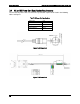

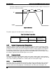
Table Of Contents
- 1. Introduction
- 2. Product Family Overview
- 3. Power Subsystem
- 3.1 Mechanical Overview
- 3.2 Power Connectors
- 3.3 Power Supply Module Efficiency
- 3.4 AC and DC Power Cord Specification Requirements
- 3.5 AC Input Specifications
- 3.5.1 Power Factor
- 3.5.2 AC Input Voltage Specification
- 3.5.3 AC Line Isolation Requirements
- 3.5.4 AC Line Dropout/Holdup
- 3.5.5 AC Line Fuse
- 3.5.6 AC Inrush
- 3.5.7 AC Line Transient Specification
- 3.5.8 Susceptibility Requirements
- 3.5.9 Electrostatic Discharge Susceptibility
- 3.5.10 Fast Transient/Burst
- 3.5.11 Radiated Immunity
- 3.5.12 Surge Immunity
- 3.5.13 Power Recovery
- 3.5.14 Voltage Interruptions
- 3.5.15 Protection Circuits
- 3.5.16 Over-current Protection (OCP)
- 3.5.17 Over-voltage Protection (OVP)
- 3.5.18 Over-temperature Protection (OTP)
- 3.6 1600W DC Power Supply Support
- 3.6.1 Power Supply Module Efficiency
- 3.6.2 DC Inlet Connector
- 3.6.3 DC Input Voltage Specification
- 3.6.4 DC Holdup/Dropout Time
- 3.6.5 DC Line Fuse
- 3.6.6 DC Inrush
- 3.6.7 DC Line Surge Voltages (Line Transients)
- 3.6.8 Residual Voltage Immunity in Standby Mode
- 3.6.9 Protection Circuits
- 3.6.10 Over Temperature Protection (OTP)
- 3.7 Cold Redundancy Support
- 3.8 Closed Loop System Throttling (CLST)
- 3.9 Smart Ride Through (SmaRT)
- 3.10 Power Supply Status LED
- 4. Thermal Management
- 5. System Storage and Peripheral Drive Bays Overview
- 6. Storage Controller Options Overview
- 7. Front Control Panel and I/O Panel Overview
- 8. Intel® Local Control Panel
- 9. PCI Riser Card Support
- 10. Additonal System Boards
- 11. Front Panel
- 12. IO Module Support
- 13. Intel® Intelligent Power Node Manager (NM)
- Appendix A: Integration and Usage Tip
- Appendix B: POST Code Diagnostic LED Decoder
- Appendix C: POST Code Errors
- Glossary
- Reference Documents
Power Subsystem Intel® Server System R2000LH2/T2 Product Family TPS
Revision 1.0
28
Practically a blackout of any duration does not damage the power supply in any way and
not cause a latch off condition.
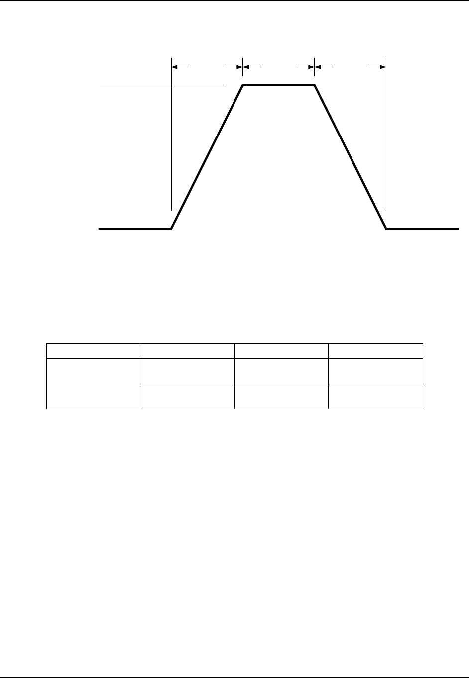
<= 5.0ms 5.0ms <= 5.0ms
0V
- 48VDC
Rise Time Fall Time
Figure 19. 0VDC Test
The power supply can also withstand the following transients.
Table 19. Line Voltage Transient Limits
Duration
Slope/Rate
Output
Performance Criteria
200µs max
-48V
→
-30V w/
+2V/µs
Rated DC Voltages
No loss of function
or performance
-30V
→
-48V w/ -
2V/µs
Rated DC Voltages
No loss of function
or performance
3.6.8
Residual Voltage Immunity in Standby Mode
The power supply is immune to any residual voltage placed on its outputs (typically a leakage
voltage through the system from standby output) up to 500mV. There is neither additional heat
generated, nor stressing of any internal components with this voltage applied to any individual
or all outputs simultaneously. It also does not trip the protection circuits during turn on. The
residual voltage at the power supply outputs for no load condition will not exceed 100mV when
AC voltage is applied and the PSON# signal is de-asserted.
3.6.9
Protection Circuits
The protection circuits inside the power supply cause only the power supply’s main outputs to
shut down. If the power supply latches off due to a protection circuit tripping, a DC cycle OFF for
15sec and a PSON# cycle HIGH for 1sec will be able to reset the power supply.
3.6.9.1
Current Limit (OCP)
The power supply has current limit to prevent the outputs from exceeding the values shown in
table below. If the current limits are exceeded, the power supply will shut down and latch off.
The latch will be cleared by toggling the PSON# signal or by a DC power interruption. The