
Technical Product Specification

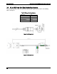
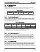
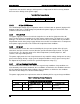
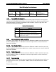
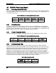

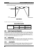
Table Of Contents
- 1. Introduction
- 2. Product Family Overview
- 3. Power Subsystem
- 3.1 Mechanical Overview
- 3.2 Power Connectors
- 3.3 Power Supply Module Efficiency
- 3.4 AC and DC Power Cord Specification Requirements
- 3.5 AC Input Specifications
- 3.5.1 Power Factor
- 3.5.2 AC Input Voltage Specification
- 3.5.3 AC Line Isolation Requirements
- 3.5.4 AC Line Dropout/Holdup
- 3.5.5 AC Line Fuse
- 3.5.6 AC Inrush
- 3.5.7 AC Line Transient Specification
- 3.5.8 Susceptibility Requirements
- 3.5.9 Electrostatic Discharge Susceptibility
- 3.5.10 Fast Transient/Burst
- 3.5.11 Radiated Immunity
- 3.5.12 Surge Immunity
- 3.5.13 Power Recovery
- 3.5.14 Voltage Interruptions
- 3.5.15 Protection Circuits
- 3.5.16 Over-current Protection (OCP)
- 3.5.17 Over-voltage Protection (OVP)
- 3.5.18 Over-temperature Protection (OTP)
- 3.6 1600W DC Power Supply Support
- 3.6.1 Power Supply Module Efficiency
- 3.6.2 DC Inlet Connector
- 3.6.3 DC Input Voltage Specification
- 3.6.4 DC Holdup/Dropout Time
- 3.6.5 DC Line Fuse
- 3.6.6 DC Inrush
- 3.6.7 DC Line Surge Voltages (Line Transients)
- 3.6.8 Residual Voltage Immunity in Standby Mode
- 3.6.9 Protection Circuits
- 3.6.10 Over Temperature Protection (OTP)
- 3.7 Cold Redundancy Support
- 3.8 Closed Loop System Throttling (CLST)
- 3.9 Smart Ride Through (SmaRT)
- 3.10 Power Supply Status LED
- 4. Thermal Management
- 5. System Storage and Peripheral Drive Bays Overview
- 6. Storage Controller Options Overview
- 7. Front Control Panel and I/O Panel Overview
- 8. Intel® Local Control Panel
- 9. PCI Riser Card Support
- 10. Additonal System Boards
- 11. Front Panel
- 12. IO Module Support
- 13. Intel® Intelligent Power Node Manager (NM)
- Appendix A: Integration and Usage Tip
- Appendix B: POST Code Diagnostic LED Decoder
- Appendix C: POST Code Errors
- Glossary
- Reference Documents

Power Subsystem Intel® Server System R2000LH2/T2 Product Family TPS
Revision 1.0
26
3.6
1600W DC Power Supply Support
3.6.1
Power Supply Module Efficiency
The following table provides the required minimum efficiency level at various loading conditions.
These are provided at three different load levels: 100%, 50%, and 20%. The input voltage is set
to -53VDC during the test.
Table 16. 1600 Watt (DC) Power Supply Efficiency (Platinum)
Loading
100% of
maximum
50% of
maximum
20% of
maximum
10% of
maximum
Minimum
Efficiency
88%
92%
88%
80%
3.6.2
DC Inlet Connector
The power supply has the -48VDC input fused. The fusing is acceptable for all safety agency
requirements. The DC inrush current does not cause the fuse to blow under any conditions. No
protection circuits in the power supply will cause the DC fuse to blow unless a component in the
power supply has failed. This includes DC output load short conditions.
3.6.3
DC Input Voltage Specification
The power supply operates within all specified limits over the following input voltage range.
Table 17. 1600 Watt (DC) Power Supply Efficiency (Platinum)
Parameter
Minimum
Rated
Maximum
Maximum Input
Current
DC Voltage
-38VDC
-48VDC/-60VDC
-75VDC
TBD
3.6.4
DC Holdup/Dropout Time
During a DC dropout of 0.2ms or less the power supply meets dynamic voltage regulation
requirements for every rated load condition. A DC line dropout of 0.2ms or less does not cause
tripping of control signals or protection circuits. Repeated every 10 seconds starting at the min
input voltage DC line dropout does not damage the power supply under any specified load
conditions. The PWOK signal does not go to a low state under these conditions. DC dropout
transients in excess of 0.2 milliseconds may cause shutdown of the PS or out of regulation
conditions, but do not damage the power supply. The power supply recovers and meets all turn
on requirements for DC dropouts that last longer than 0.2ms. The power supply meets the DC
dropout requirement over rated DC voltages and output loading conditions.
Table 18. DC Holdup/Dropout Time
Power Supply
Wattage
Loading
Holdup Time
1600W
1200W (75%)
0.2 msec