
Technical Product Specification
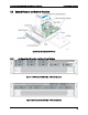
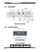


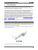
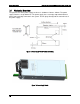
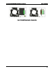
Table Of Contents
- 1. Introduction
- 2. Product Family Overview
- 3. Power Subsystem
- 3.1 Mechanical Overview
- 3.2 Power Connectors
- 3.3 Power Supply Module Efficiency
- 3.4 AC and DC Power Cord Specification Requirements
- 3.5 AC Input Specifications
- 3.5.1 Power Factor
- 3.5.2 AC Input Voltage Specification
- 3.5.3 AC Line Isolation Requirements
- 3.5.4 AC Line Dropout/Holdup
- 3.5.5 AC Line Fuse
- 3.5.6 AC Inrush
- 3.5.7 AC Line Transient Specification
- 3.5.8 Susceptibility Requirements
- 3.5.9 Electrostatic Discharge Susceptibility
- 3.5.10 Fast Transient/Burst
- 3.5.11 Radiated Immunity
- 3.5.12 Surge Immunity
- 3.5.13 Power Recovery
- 3.5.14 Voltage Interruptions
- 3.5.15 Protection Circuits
- 3.5.16 Over-current Protection (OCP)
- 3.5.17 Over-voltage Protection (OVP)
- 3.5.18 Over-temperature Protection (OTP)
- 3.6 1600W DC Power Supply Support
- 3.6.1 Power Supply Module Efficiency
- 3.6.2 DC Inlet Connector
- 3.6.3 DC Input Voltage Specification
- 3.6.4 DC Holdup/Dropout Time
- 3.6.5 DC Line Fuse
- 3.6.6 DC Inrush
- 3.6.7 DC Line Surge Voltages (Line Transients)
- 3.6.8 Residual Voltage Immunity in Standby Mode
- 3.6.9 Protection Circuits
- 3.6.10 Over Temperature Protection (OTP)
- 3.7 Cold Redundancy Support
- 3.8 Closed Loop System Throttling (CLST)
- 3.9 Smart Ride Through (SmaRT)
- 3.10 Power Supply Status LED
- 4. Thermal Management
- 5. System Storage and Peripheral Drive Bays Overview
- 6. Storage Controller Options Overview
- 7. Front Control Panel and I/O Panel Overview
- 8. Intel® Local Control Panel
- 9. PCI Riser Card Support
- 10. Additonal System Boards
- 11. Front Panel
- 12. IO Module Support
- 13. Intel® Intelligent Power Node Manager (NM)
- Appendix A: Integration and Usage Tip
- Appendix B: POST Code Diagnostic LED Decoder
- Appendix C: POST Code Errors
- Glossary
- Reference Documents
Intel® Server System R2000LH2/T2 Product Family TPS Power Subsystem
Revision 1.0
15
3. Power Subsystem
This chapter provides a high level overview of the power management features and
specification data for the power supply options available for this server product. Specification
variations are identified for each supported power supply.
The server system can have up to two power supply modules installed, supporting the following
power supply configurations: 1+0 (single power supply), 1+1 redundant power, and 2+0
combined power (non-redundant).The 1+1 redundant power and 2+0 combined power
configurations are automatically configured depending on the total power draw of the system. If
the total system power draw exceeds the power capacity of a single power supply module, the
power from the second power supply module will be utilized. If this occurs, power redundancy
will be lost. In a 2+0 power configuration, the total power available may be less than twice the
rated power of the installed power supply modules due to the amount of heat produced with
both supplies providing peak power. If system thermals exceed programmed limits, platform
management will attempt to keep the system operational. See
Closed Loop System Throttling
(CLST) and Thermal Management for details.
There are two power supply options available for this server product: 1600W AC and 1600W
DC.
Note: Mixing of AC and DC power supplies in the same system is unsupported.
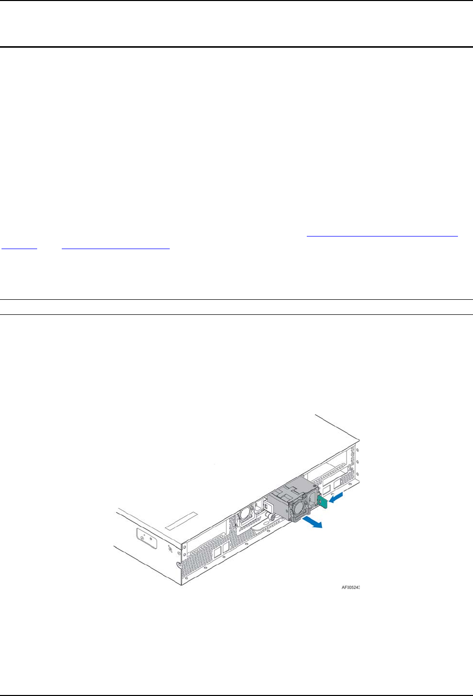
The power supplies are modular, allowing for tool-less insertion and extraction from a bay in the
back of the chassis. When inserted, the card edge connector of the power supply mates blindly
to a matching slot connector on the server board.
In the event of a power supply failure, redundant 1+1 power supply configurations support hot-
swap extraction and insertion.
Figure 12. Power Supply
The AC input is auto-ranging and power factor corrected.