
Technical Product Specification


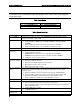


Table Of Contents
- 1. Introduction
- 2. Product Family Overview
- 3. Power Subsystem
- 3.1 Mechanical Overview
- 3.2 Power Connectors
- 3.3 Power Supply Module Efficiency
- 3.4 AC and DC Power Cord Specification Requirements
- 3.5 AC Input Specifications
- 3.5.1 Power Factor
- 3.5.2 AC Input Voltage Specification
- 3.5.3 AC Line Isolation Requirements
- 3.5.4 AC Line Dropout/Holdup
- 3.5.5 AC Line Fuse
- 3.5.6 AC Inrush
- 3.5.7 AC Line Transient Specification
- 3.5.8 Susceptibility Requirements
- 3.5.9 Electrostatic Discharge Susceptibility
- 3.5.10 Fast Transient/Burst
- 3.5.11 Radiated Immunity
- 3.5.12 Surge Immunity
- 3.5.13 Power Recovery
- 3.5.14 Voltage Interruptions
- 3.5.15 Protection Circuits
- 3.5.16 Over-current Protection (OCP)
- 3.5.17 Over-voltage Protection (OVP)
- 3.5.18 Over-temperature Protection (OTP)
- 3.6 1600W DC Power Supply Support
- 3.6.1 Power Supply Module Efficiency
- 3.6.2 DC Inlet Connector
- 3.6.3 DC Input Voltage Specification
- 3.6.4 DC Holdup/Dropout Time
- 3.6.5 DC Line Fuse
- 3.6.6 DC Inrush
- 3.6.7 DC Line Surge Voltages (Line Transients)
- 3.6.8 Residual Voltage Immunity in Standby Mode
- 3.6.9 Protection Circuits
- 3.6.10 Over Temperature Protection (OTP)
- 3.7 Cold Redundancy Support
- 3.8 Closed Loop System Throttling (CLST)
- 3.9 Smart Ride Through (SmaRT)
- 3.10 Power Supply Status LED
- 4. Thermal Management
- 5. System Storage and Peripheral Drive Bays Overview
- 6. Storage Controller Options Overview
- 7. Front Control Panel and I/O Panel Overview
- 8. Intel® Local Control Panel
- 9. PCI Riser Card Support
- 10. Additonal System Boards
- 11. Front Panel
- 12. IO Module Support
- 13. Intel® Intelligent Power Node Manager (NM)
- Appendix A: Integration and Usage Tip
- Appendix B: POST Code Diagnostic LED Decoder
- Appendix C: POST Code Errors
- Glossary
- Reference Documents

Product Family Overview Intel® Server System R2000LH2/T2 Product Family TPS
Revision 1.0
8
Note:
1. Intel Corporation server boards contain a number of high-density VLSI and power delivery components that
need adequate airflow to cool. Intel ensures through its own chassis development and testing that when
Intel
®
server building blocks are used together, the fully integrated system will meet the intended thermal
requirements of these components. It is the responsibility of the system integrator who chooses not to use
Intel developed server building blocks to consult vendor datasheets and operating parameters to determine
the amount of airflow required for their specific application and environmental conditions. Intel Corporation
cannot be held responsible if components fail or the server board does not operate correctly when used
outside any of its published operating or non-operating limits.
Disclaimer Note: Intel ensures the unpackaged server board and system meet the shock
requirement mentioned above through its own chassis development and system configuration. It
is the responsibility of the system integrator to determine the proper shock level of the board
and system if the system integrator chooses different system configuration or different chassis.
Intel Corporation cannot be held responsible, if components fail or the server board does not
operate correctly when used outside any of its published operating or non-operating limits.
See the Intel
®
Server Board S4600LH2/T2 Power Budget and Thermal Configuration Guidelines
Tool for system configuration requirements and limitations.