
Technical Product Specification


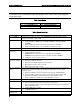


Table Of Contents
- 1. Introduction
- 2. Product Family Overview
- 3. Power Subsystem
- 3.1 Mechanical Overview
- 3.2 Power Connectors
- 3.3 Power Supply Module Efficiency
- 3.4 AC and DC Power Cord Specification Requirements
- 3.5 AC Input Specifications
- 3.5.1 Power Factor
- 3.5.2 AC Input Voltage Specification
- 3.5.3 AC Line Isolation Requirements
- 3.5.4 AC Line Dropout/Holdup
- 3.5.5 AC Line Fuse
- 3.5.6 AC Inrush
- 3.5.7 AC Line Transient Specification
- 3.5.8 Susceptibility Requirements
- 3.5.9 Electrostatic Discharge Susceptibility
- 3.5.10 Fast Transient/Burst
- 3.5.11 Radiated Immunity
- 3.5.12 Surge Immunity
- 3.5.13 Power Recovery
- 3.5.14 Voltage Interruptions
- 3.5.15 Protection Circuits
- 3.5.16 Over-current Protection (OCP)
- 3.5.17 Over-voltage Protection (OVP)
- 3.5.18 Over-temperature Protection (OTP)
- 3.6 1600W DC Power Supply Support
- 3.6.1 Power Supply Module Efficiency
- 3.6.2 DC Inlet Connector
- 3.6.3 DC Input Voltage Specification
- 3.6.4 DC Holdup/Dropout Time
- 3.6.5 DC Line Fuse
- 3.6.6 DC Inrush
- 3.6.7 DC Line Surge Voltages (Line Transients)
- 3.6.8 Residual Voltage Immunity in Standby Mode
- 3.6.9 Protection Circuits
- 3.6.10 Over Temperature Protection (OTP)
- 3.7 Cold Redundancy Support
- 3.8 Closed Loop System Throttling (CLST)
- 3.9 Smart Ride Through (SmaRT)
- 3.10 Power Supply Status LED
- 4. Thermal Management
- 5. System Storage and Peripheral Drive Bays Overview
- 6. Storage Controller Options Overview
- 7. Front Control Panel and I/O Panel Overview
- 8. Intel® Local Control Panel
- 9. PCI Riser Card Support
- 10. Additonal System Boards
- 11. Front Panel
- 12. IO Module Support
- 13. Intel® Intelligent Power Node Manager (NM)
- Appendix A: Integration and Usage Tip
- Appendix B: POST Code Diagnostic LED Decoder
- Appendix C: POST Code Errors
- Glossary
- Reference Documents
Intel® Server System R2000LH2/T2 Product Family TPS Product Family Overview
Revision 1.0
7
2.2
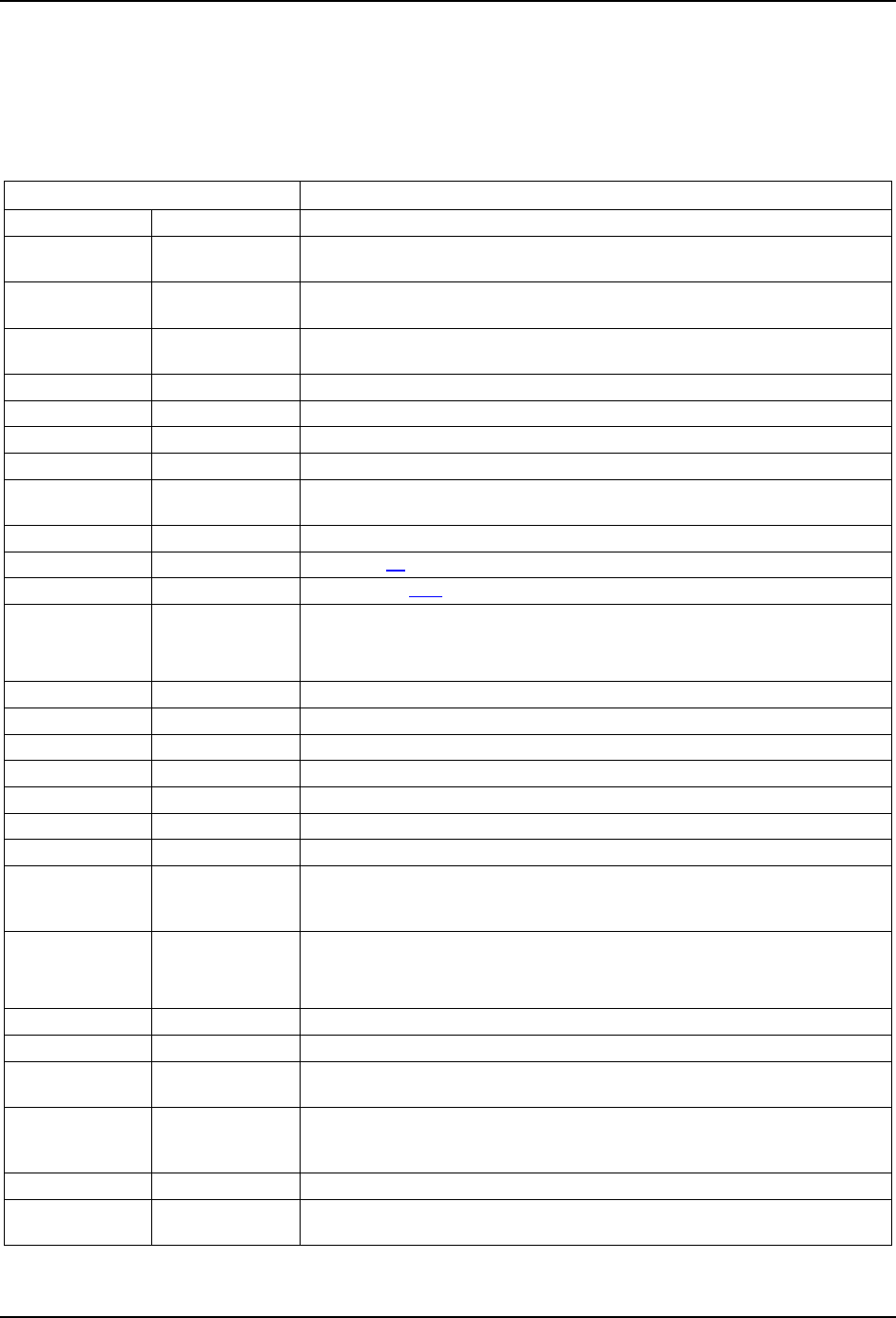
System Level Environmental Limits
The following table defines the system level operating and non-operating environmental limits.
Table 3. System Environmental Limits Summary
Parameter
Limits
Temperature
Operating
ASHRAE Class A2 – Continuous Operation. 10ºC to 35ºC
1
(50ºF to 95ºF)
with the maximum rate of change not to exceed 10°C per hour
ASHRAE Class A3 – Includes operation up to 40ºC for up to 900 hrs. per
year
ASHRAE Class A4 – Includes operation up to 45ºC for up to 90 hrs. per
year
Shipping
-40ºC to 70ºC (-40ºF to 158ºF)
Altitude
Operating
Support operation up to 3050m with ASHRAE class deratings
Humidity
Shipping
50% to 90%, non-condensing with a maximum wet bulb of 28°C (at
temperatures from 25°C to 35°C)
Shock
Operating
Half sine, 2g, 11 mSec
Unpackaged
Trapezoidal, 25 g, velocity change is based on packaged weight
Packaged
Product Weight: ≥ 40 to < 80
Non-palletized Free Fall Height = 18 inches
Palletized (single product) Free Fall Height = NA
Vibration
Unpackaged
5 Hz to 500 Hz 2.20 g RMS random
Packaged
5 Hz to 500 Hz 1.09 g RMS random
AC-DC
Voltage
90 Hz to 132 V and 180 V to 264 V
Frequency
47 Hz to 63 Hz
Source Interrupt
No loss of data for power line drop-out of 12 mSec
Surge Non-
operating and
operating
Unidirectional
Line to earth
Only
AC Leads 2.0 kV
I/O Leads 1.0 kV
DC Leads 0.5 kV
ESD
Air Discharged
12.0 kV
Contact
Discharge
8.0 kV
Acoustics
Sound Power
Measured
Power in Watts
<300 W ≥300 W ≥600 W ≥1000 W
Servers/Rack
Mount BA
7.0 7.0 7.0 7.0