
Technical Product Specification
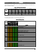
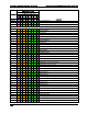

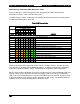
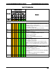


Table Of Contents
- 1. Introduction
- 2. Product Family Overview
- 3. Power Subsystem
- 3.1 Mechanical Overview
- 3.2 Power Connectors
- 3.3 Power Supply Module Efficiency
- 3.4 AC and DC Power Cord Specification Requirements
- 3.5 AC Input Specifications
- 3.5.1 Power Factor
- 3.5.2 AC Input Voltage Specification
- 3.5.3 AC Line Isolation Requirements
- 3.5.4 AC Line Dropout/Holdup
- 3.5.5 AC Line Fuse
- 3.5.6 AC Inrush
- 3.5.7 AC Line Transient Specification
- 3.5.8 Susceptibility Requirements
- 3.5.9 Electrostatic Discharge Susceptibility
- 3.5.10 Fast Transient/Burst
- 3.5.11 Radiated Immunity
- 3.5.12 Surge Immunity
- 3.5.13 Power Recovery
- 3.5.14 Voltage Interruptions
- 3.5.15 Protection Circuits
- 3.5.16 Over-current Protection (OCP)
- 3.5.17 Over-voltage Protection (OVP)
- 3.5.18 Over-temperature Protection (OTP)
- 3.6 1600W DC Power Supply Support
- 3.6.1 Power Supply Module Efficiency
- 3.6.2 DC Inlet Connector
- 3.6.3 DC Input Voltage Specification
- 3.6.4 DC Holdup/Dropout Time
- 3.6.5 DC Line Fuse
- 3.6.6 DC Inrush
- 3.6.7 DC Line Surge Voltages (Line Transients)
- 3.6.8 Residual Voltage Immunity in Standby Mode
- 3.6.9 Protection Circuits
- 3.6.10 Over Temperature Protection (OTP)
- 3.7 Cold Redundancy Support
- 3.8 Closed Loop System Throttling (CLST)
- 3.9 Smart Ride Through (SmaRT)
- 3.10 Power Supply Status LED
- 4. Thermal Management
- 5. System Storage and Peripheral Drive Bays Overview
- 6. Storage Controller Options Overview
- 7. Front Control Panel and I/O Panel Overview
- 8. Intel® Local Control Panel
- 9. PCI Riser Card Support
- 10. Additonal System Boards
- 11. Front Panel
- 12. IO Module Support
- 13. Intel® Intelligent Power Node Manager (NM)
- Appendix A: Integration and Usage Tip
- Appendix B: POST Code Diagnostic LED Decoder
- Appendix C: POST Code Errors
- Glossary
- Reference Documents
Intel® Server System R2000LH2/T2 Product Family TPS Appendix B: POST Code Diagnostic LED Decoder
Revision 1.0
103
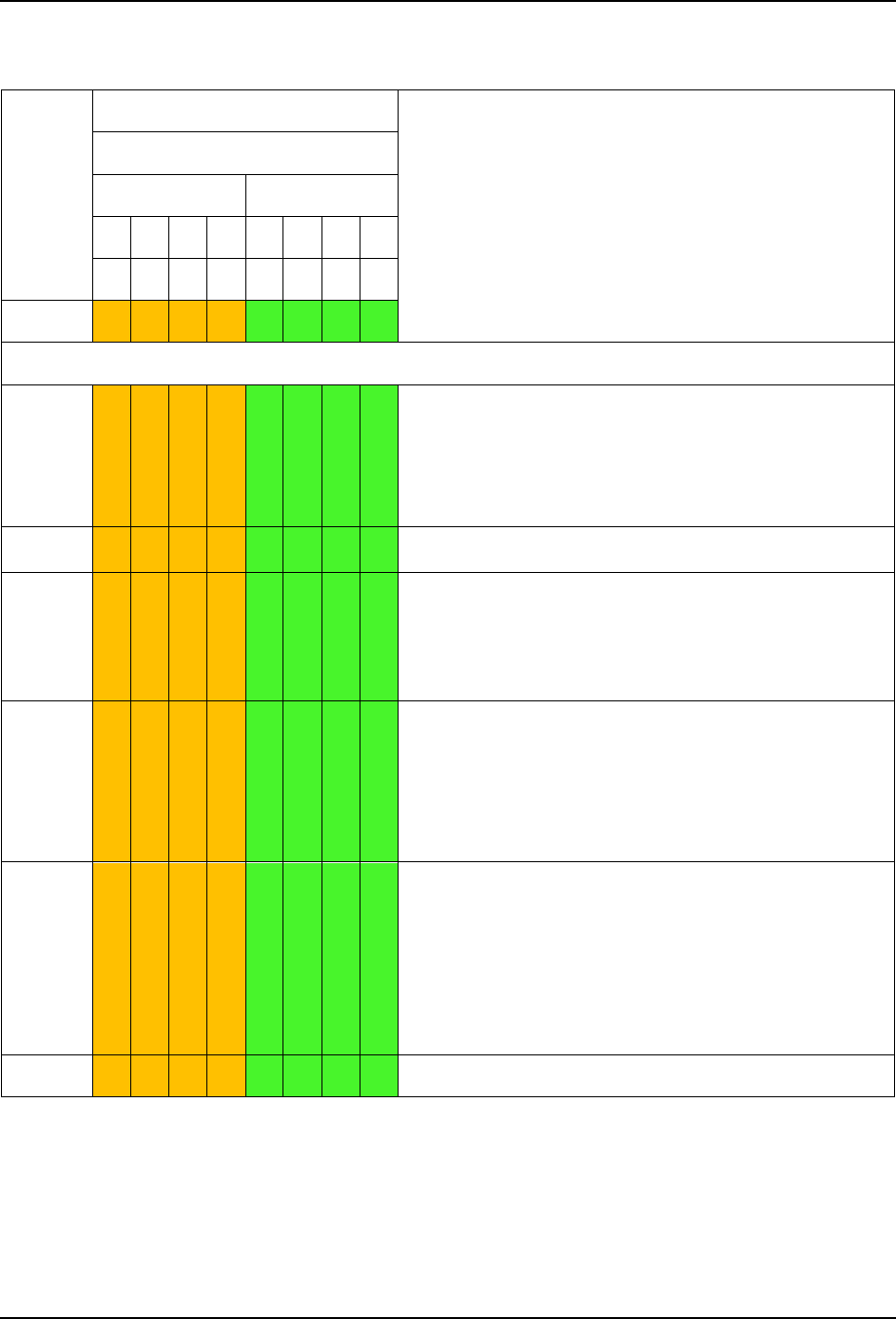
Table 47. MRC Fatal Error Codes
Checkpoint
Diagnostic LED Decoder
Description
1 = LED On, 0 = LED Off
Upper Nibble
Lower Nibble
MSB
LSB
8h
4h
2h
1h
8h
4h
2h
1h
LED
#7
#6
#5
#4
#3
#2
#1
#0
MRC Fatal Error Codes
E8h
1 1 1 0 1 0 0 0
No usable memory error
01h = No memory was detected from the SPD read, or invalid
config that causes no operable memory.
02h = Memory DIMMs on all channels of all sockets are disabled
due to hardware memtest error.
3h = No memory installed. All channels are disabled.
E9h
1 1 1 0 1 0 0 1
Memory is locked by Intel
®
Trusted Execution Technology and is
inaccessible
EAh
1 1 1 0 1 0 1 0
DDR3 channel training error
01h = Error on read DQ/DQS (Data/Data Strobe) init
02h = Error on Receive Enable
3h = Error on Write Leveling
04h = Error on write DQ/DQS (Data/Data Strobe
EBh
1 1 1 0 1 0 1 1
Memory test failure
01h = Software memtest failure.
02h = Hardware memtest failed.
03h = Hardware Memtest failure in Lockstep Channel mode
requiring a channel to be disabled. This is a fatal error which
requires a reset and calling MRC with a different RAS mode to
retry.
EDh
1 1 1 0 1 1 0 1
DIMM configuration population error
01h = Different DIMM types (UDIMM, RDIMM, LRDIMM) are
detected installed in the system.
02h = Violation of DIMM population rules.
03h = The 3rd DIMM slot cannot be populated when QR DIMMs
are installed.
04h = UDIMMs are not supported in the 3rd DIMM slot.
05h = Unsupported DIMM Voltage.
EFh
1 1 1 0 1 1 1 1
Indicates a CLTT table structure error