
Technical Product Specification
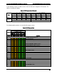
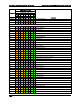

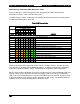
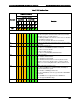


Table Of Contents
- 1. Introduction
- 2. Product Family Overview
- 3. Power Subsystem
- 3.1 Mechanical Overview
- 3.2 Power Connectors
- 3.3 Power Supply Module Efficiency
- 3.4 AC and DC Power Cord Specification Requirements
- 3.5 AC Input Specifications
- 3.5.1 Power Factor
- 3.5.2 AC Input Voltage Specification
- 3.5.3 AC Line Isolation Requirements
- 3.5.4 AC Line Dropout/Holdup
- 3.5.5 AC Line Fuse
- 3.5.6 AC Inrush
- 3.5.7 AC Line Transient Specification
- 3.5.8 Susceptibility Requirements
- 3.5.9 Electrostatic Discharge Susceptibility
- 3.5.10 Fast Transient/Burst
- 3.5.11 Radiated Immunity
- 3.5.12 Surge Immunity
- 3.5.13 Power Recovery
- 3.5.14 Voltage Interruptions
- 3.5.15 Protection Circuits
- 3.5.16 Over-current Protection (OCP)
- 3.5.17 Over-voltage Protection (OVP)
- 3.5.18 Over-temperature Protection (OTP)
- 3.6 1600W DC Power Supply Support
- 3.6.1 Power Supply Module Efficiency
- 3.6.2 DC Inlet Connector
- 3.6.3 DC Input Voltage Specification
- 3.6.4 DC Holdup/Dropout Time
- 3.6.5 DC Line Fuse
- 3.6.6 DC Inrush
- 3.6.7 DC Line Surge Voltages (Line Transients)
- 3.6.8 Residual Voltage Immunity in Standby Mode
- 3.6.9 Protection Circuits
- 3.6.10 Over Temperature Protection (OTP)
- 3.7 Cold Redundancy Support
- 3.8 Closed Loop System Throttling (CLST)
- 3.9 Smart Ride Through (SmaRT)
- 3.10 Power Supply Status LED
- 4. Thermal Management
- 5. System Storage and Peripheral Drive Bays Overview
- 6. Storage Controller Options Overview
- 7. Front Control Panel and I/O Panel Overview
- 8. Intel® Local Control Panel
- 9. PCI Riser Card Support
- 10. Additonal System Boards
- 11. Front Panel
- 12. IO Module Support
- 13. Intel® Intelligent Power Node Manager (NM)
- Appendix A: Integration and Usage Tip
- Appendix B: POST Code Diagnostic LED Decoder
- Appendix C: POST Code Errors
- Glossary
- Reference Documents
Appendix B: POST Code Diagnostic LED Decoder Intel® Server System R2000LH2/T2 Product Family TPS
Revision 1.0
102
POST Memory Initialization MRC Diagnostic Codes
There are two types of POST Diagnostic Codes displayed by the MRC during memory
initialization; Progress Codes and Fatal Error Codes.
The MRC Progress Codes are displays to the Diagnostic LEDs that show the execution point in
the MRC operational path at each step.
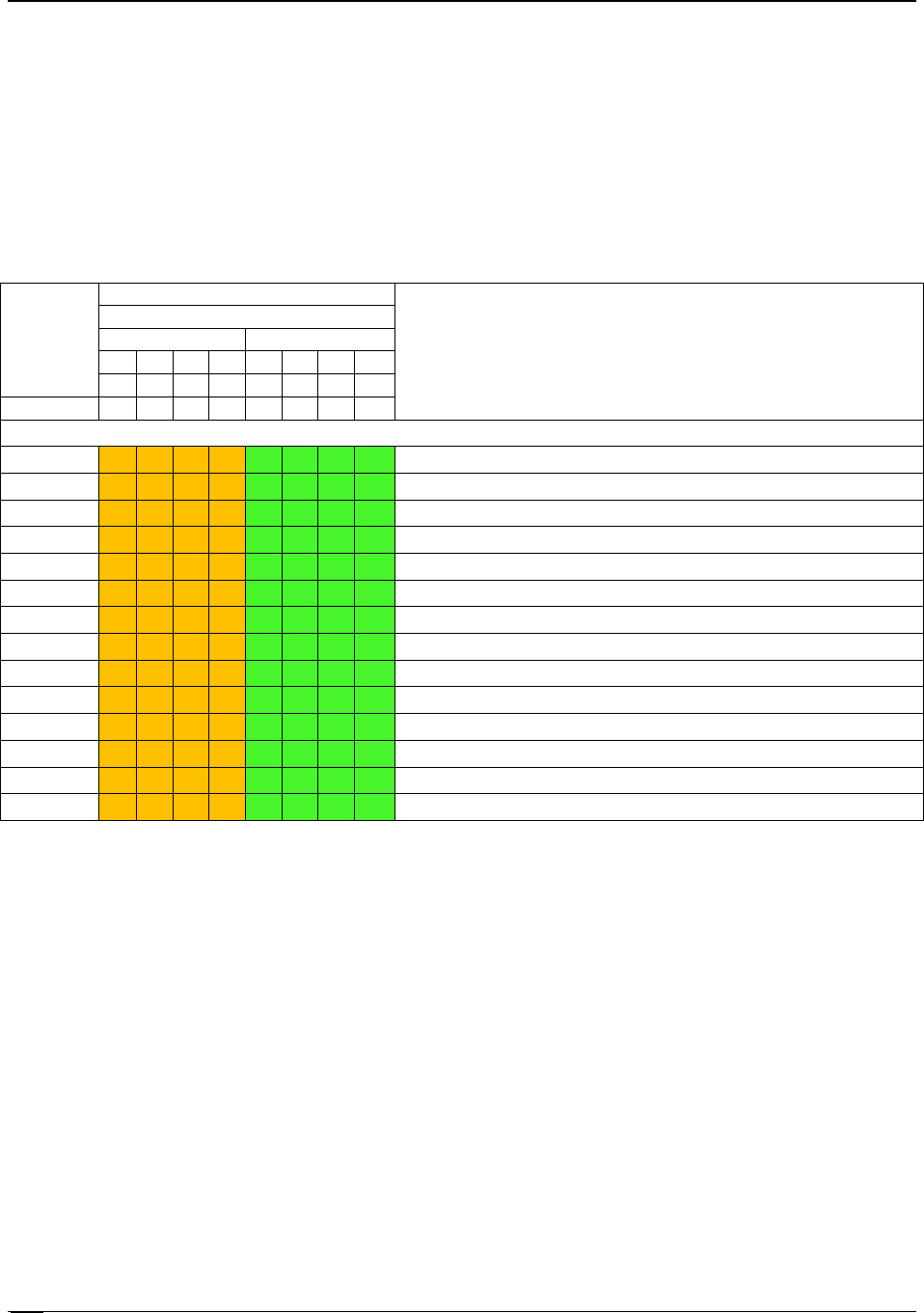
Table 46. MRC Progress Codes
Checkpoint
Diagnostic LED Decoder
Description
1 = LED On, 0 = LED Off
Upper Nibble
Lower Nibble
MSB
LSB
8h
4h
2h
1h
8h
4h
2h
1h
LED #
#7
#6
#5
#4
#3
#2
#1
#0
MRC Progress Codes
B0h
1
0
1
1
0
0
0
0
Detect DIMM population
B1h
1
0
1
1
0
0
0
1
Set DDR3 frequency
B2h
1
0
1
1
0
0
1
0
Gather remaining SPD data
B3h
1
0
1
1
0
0
1
1
Program registers on the memory controller level
B4h
1
0
1
1
0
1
0
0
Evaluate RAS modes and save rank information
B5h
1
0
1
1
0
1
0
1
Program registers on the channel level
B6h
1
0
1
1
0
1
1
0
Perform the JEDEC defined initialization sequence
B7h
1
0
1
1
0
1
1
1
Train DDR3 ranks
B8h
1
0
1
1
1
0
0
0
Initialize CLTT/OLTT
B9h
1
0
1
1
1
0
0
1
Hardware memory test and init
BAh
1
0
1
1
1
0
1
0
Execute software memory init
BBh
1
0
1
1
1
0
1
1
Program memory map and interleaving
BCh
1
0
1
1
1
1
0
0
Program RAS configuration
BFh
1
0
1
1
1
1
1
1
MRC is done
Memory Initialization at the beginning of POST includes multiple functions, including discovery,
channel training, validation that the DIMM population is acceptable and functional, initialization
of the IMC and other hardware settings, and initialization of applicable RAS configurations.
When a major memory initialization error occurs and prevents the system from booting with data
integrity, a beep code is generated, the MRC will display a fatal error code on the diagnostic
LEDs, and a system halt command is executed. Fatal MRC error halts do NOT change the state
of the System Status LED, and they do NOT get logged as SEL events. The following table lists
all MRC fatal errors that are displayed to the Diagnostic LEDs.